Profiles
Profiles are a set of general configuration settings that can be swiftly and easily applied to all devices associated with the Profile so all devices are configured identically as a group.
Creating a Profile
After a profile is created, you can configure network routing rules and security features within each profile.
Note: Profiles are created for individual organizations. In order to configure Profiles, select the desired organization from the drop-down menu at the top of the page.
- Navigate to Configure > Gateway > Profiles.
- Click Create Profile.
- Enter a name for the Profile and choose the device model.
Note: The Profile can only be used for the selected device model type. - Select the Access Level for the accessibility level of the profile under the Organization, Site tag, or Site.
- [Optional] Select Clone from existing profile and choose a Profile from the drop-down menu to clone an existing Profile. Or select Use default configuration to apply the default configurations. The page provides modification options to let you modify configurations later.
- Click Create Profile.
Deleting Profiles
- Navigate to Configure > Gateway > Profiles.
- From the Profile list, click the checkbox next to the Profiles you wish to delete.
- Click Delete profile at the top of the table.
- When prompted to confirm, click Yes.
Pushing Configuration Changes
The Push Configuration function allows you to quickly apply Profile configuration changes to all devices using this Profile.
Note: Changes made to a Profile’s settings will be pushed to all associated devices after the user selects Push Configuration.
- Navigate to Configure > Gateway > Profiles.
- From the Profile list, click the checkbox next to the Profiles you wish to push the configuration to apply it to the associated devices of the configured model.
- Click Push Configuration at the top of the table.
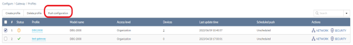
- Select either Push Configuration Now or Schedule a Configuration Pushing Time to apply the configuration changes at a later time. The schedule will be reflected in the Scheduled Push column of the Profiles list.
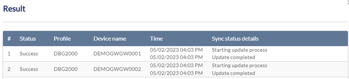
- The Result windows appears to display the push configuration status, affected profiles and devices, time of the configuration change, and details about the update process.
Configuring Network Settings
From the Network window, you can configure basic port settings and advanced settings for routing and traffic management.
- Navigate to Configure > Gateway > Profiles.
- From the Profile list, click Network under the Actions column of the Profile you wish to edit.
To configure a port’s basic settings:
- Select the Network tab at the top. The LAN ports of the device are displayed along with their information shown in the table below.
Note: The Profile can only be used for the selected device model type. - Under Port Configuration, select a port and click EDIT under Actions.
Specify the following information for the selected LAN port:
Interface Type
Select the connection type: LAN or DMZ.
Interface Name
Enter a name to identify this interface.
Bridge Network
Enable or disable bridging with another network. Configure the interface with more settings below if bridging is not enabled.
IP Address/Subnet Mask
Enter an IP address with subnet mask.
DHCP mode
Enable or disable DHCP service for IP address assignment.
DHCP server
Enter the following information if DHCP server is selected.
Domain name: Assign a domain name for DHCP service.
Starting IP address/Ending IP address: Enter the range of IP addresses that can be assigned dynamically.
Default gateway: Assign a default gateway for DHCP service.
DNS server: Configure DNS by specifying a static DNS server, DNS setting from the ISP, or using DNS proxy. For static DNS, enter the DNS servers or WIN server IP address.
Lease Time: Enter a time value of 1 to 10080 minutes.
Allow ping from LAN/DMZ
Enable or disable ping command executed from this port.
DHCP Relay
Enter the remote DHCP server address if DHCP relay is selected.
DNS proxy
Enable or disable DNS proxy.
For a WAN port (if the device supports this feature), configure the following:
Interface Type
Select the WAN interface for configuration.
Connection Type
Select the connection method: DHCP, Static IP, PPPoE, PPTP, L2TP, DS-Lite/IPIP, or MAP-E. For Static IP, enter the IP address/Subnet mask, Gateway IP address and Primary/Secondary DNS servers, and specify whether to keep the original MAC address as well as the MTU size. For PPPoE, select the Address mode: Dynamic IP or Static IP. For static IP, enter the IP address/Subnet mask and PPPoE connection Username and Password. Then specify the Authentication type from one of the following: None, MS-CHAPv2, MS-CHAP, CHAP, PAP, or Auto-negotiate. For Dynamic IP, you don’t need to enter the IP address/subnet information but configure all other settings as specified above. For both addressing modes, enter the Service name (optional) and select the Reconnect mode: Always on, or On demand (enter the Maximum idle time to wait before terminating the connection in minutes for this option). Then configure the DNS servers and specify whether to keep the original MAC address as well as the MTU size. For PPTP, if Static IP is selected, enter the following IP address information: IP address/Subnet mask, Gateway IP address, and Static DNS IP address. For both Address modes, enter the PPTP server name and connection Username and Password. For both modes, configure whether MPPE (Microsoft Point-to-Point Encryption (MPPE) will be used and the Reconnect mode: Always on or On demand (enter the Maximum idle time to wait before terminating the connection in minutes for this option). Then configure the DNS servers and specify whether to keep the original MAC address as well as the MTU size. For L2TP, if Static IP is selected, enter the following IP address information: IP address/Subnet mask, Gateway IP address, and Static DNS IP address. For both Address modes, enter the L2TP server name and connection Username and Password. For both modes, enter the Secret (optional) and configure the Reconnect mode: Always on or On demand (enter the Maximum idle time to wait before terminating the connection in minutes for this option). Then configure the DNS servers and specify whether to keep the original MAC address as well as the MTU size.
For DS-Lite/IPIP, select the Service Provider and Address Family Transition Router (AFTR) Addressing method. For MAP-E, select the Service Provider.
Note: Service providers are only available in specific countries.
Advanced Settings
Enable or disable the following passthroughs:
Internet Protocol Security (IPsec) which is used for securing packets exchange at the IP layer.
Point-to-Point Tunneling Protocol (PPTP) which is used for tunneling the Point-to-Point Protocol (PPP) communication in an IP network.
Layer 2 Tunneling Protocol (L2TP) which is used for implementing Point-to-Point sessions utilizing multipoint tunneling technique.
-
Click Push Configuration at the top left to apply the settings to the affected devices immediately.
Configuring the Default WAN Configuration
Note: The availability of the WAN Mode Configuration depends on device model.
- Navigate to Configure > Gateway > Profiles.
- From the Profile list, click Network under the Actions column of the Profile you wish to edit.
- Under Default WAN Configuration, select IPv4 and IPv6 default WAN port. Note that the settings or configurations here depend on the device model and firmware.
- Under WAN Mode, select a WAN mode from the available options. For Auto-rollover using WAN, select both Primary and Secondary WAN ports as well as the Health Check method. If DNS servers or Ping IP address method is selected, enter the respective server IP address as the destination to check the connectivity. Also enter the Retry interval (seconds) and Failover after (number of failed retries).
- For Load balancing, select the method (either Round robin or Spillover mode). For Round robin, configure the Health check method (or none) and enter the Retry interval (seconds) and Failover after (number of failed retries). Hence, if a WAN interface disconnects, only the alternate WAN ports will transfer traffic flows in a round robin manner. For Spillover, enter the Load tolerance (%) and Max bandwidth (Mbps) as the threshold value. Once the threshold is exceeded for a WAN port, new traffic flows will be allocated to the alternate WAN interfaces. The precedence for selection is based on the configuration of Primary, Secondary, and Tertiary WAN interface.
- Click Push Configuration at the top left to apply the settings to the affected devices immediately.
Configuring Wireless Settings
You can create multiple SSIDs under a single Profile and configure each SSID with unique settings to accommodate different wireless usage scenarios. Note that this feature is only available on supported models.
To create an SSID:
- Navigate to Configure > Gateway > Profiles.
- From the Profile list, click Network under the Actions column of the Profile you wish to edit.
- Select Wireless.
- Under SSID, click Add to add a new SSID profile setting. Enter the following information:
SSID Name
Enter a name for the SSID (1-32 characters). Band Selection
Select the radio frequency to be used for the SSID configuration: 2.4GHz and/or 5GHz.
-
Click Edit under Actions to modify an SSID profile setting. Enter the following information:
SSID Name
Enter a name for the SSID (1-32 characters).
Security
Select the security mode:
Open: Select this option for an unsecured network.
Enhanced open: This method provides protection based on opportunistic wireless encryption (OWE) and open authentication.
Enhanced Open+Open: This method provides transition from an open to Enhanced Open wireless environment.
WPA2: The Wi-Fi Protected Access II (WPA2) security protocol requires users to enter an alphanumeric passphrase or the information of a RADIUS server.
WPA/WPA2: This method allows both WPA and WPA2 clients to connect.
WPA3: WPA3 is the strongest encryption method among WPA standards.
WPA2/WPA3: This method allows both WPA2 and WPA3 clients to connect.
Authentication method
Select the respective authentication method for the security type selected above. If a RADIUS server is used in your network environment, enter the RADIUS server information (refer to Authentication Servers) as well as the Group key update interval and the encryption method.
MAC Filtering
Enable or disable MAC Filtering and select the desired filtering mechanism: MAC ACLs or RADIUS server. If MAC ACLs is selected, specify whether it is a Allow or Deny rule. For information on managing MAC ACLs, refer to MAC ACLs. If RADIUS server is selected, enter the RADIUS server information (refer to Authentication Servers).
Broadcast SSID
Enable or disable the visibility of the SSID.
Band Selection
Select the available radio frequencies that the device supports and enable or disable band steering which automatically connects newer devices to the higher frequency band available.
Guest Access Mode
Enable or disable guest access function.
Station Isolation
Enable or disable isolation of stations within the SSID so that wireless clients will not be able to communicate with each other.
NAS-IP-address (optional)
Enable the network access server IP address to let RADIUS server to choose an access policy for a connection request.
Bridge to Interface
Bridge this wireless network to a LAN/VLAN interface.
Schedule Policy
Select a pre-defined schedule policy to designate a time frame to make the configuration effective. To view all available schedule policies, go to Configure > Schedule policies. To add a new schedule policy, click Add schedule policy ( refer to Schedule Policies for more information).
- Click Next to configure more settings:
Max Client
Enter the maximum number of concurrent clients that can connect to the SSID. The maximum is 64.
Max Allowed Client Retries
Enter the maximum amount of times a client can attempt to reconnect to the SSID once the maximum client limit has been reached. After retrying the set amount times, the client will associate with the AP for a maximum of up to 128 clients.
Note: If set to 0, no additional clients will be accepted by the AP despite the amount of retries.
Max Upstream
Enter a maximum uploading bandwidth limit (in Kbps) for this SSID.
Max Downstream
Enter a maximum downloading bandwidth limit (in Kbps) for this SSID.
Max Client Upstream
Enter a maximum uploading bandwidth limit (in Kbps) for each client connected to this SSID.
Max Client Downstream
Enter a maximum downloading bandwidth limit (in Kbps) for each client connected to this SSID.
Forward Bonjour Pkts
Enable or disable the forwarding of Apple Bonjour packets from wireless clients to the rest of the network.
IGMP Snooping
Enable or disable IGMP Snooping. This allows the SSID to listen in on IGMP conversations on the network.
Max Multicast Ingress
Enter a maximum multicast ingress bandwidth limit (in Kbps).
RTS Threshold
Enter the packet size threshold to determine when the device will issue a RTS before sending the packet.
Fragmentation Threshold Limit the packet size for wireless packets transmitted in the network. Force Roaming
Enable or disable force roaming. Clients will be forced to roam to another access point once the signal strength falls below the set threshold.
Signal Strength Threshold
Enter the signal strength threshold (in dbm) for clients to start roaming.
Weak Signal Exception
Enable or disable weak signal exception. This allows clients with a weak signal to connect to the SSID after a set number of attempts.
Weak RSSI Client Associations Attempts
Enter the number of times a client with a weak signal can try to connect, after which the access point will allow the client to connect to it.
- Under Radio, configure the following information for each available radio frequency:
Radio
Enable or disable this radio frequency.
Radio Mode
Select the 802.11 mode.
Channel Bandwidth
Select the channel bandwidth. The availability of channel width depends on the selected 802.11 mode.
Tx Power
Enter the transmission power.
Auto Channel
Enable or disable auto channel. If disabled, select the channel number.
Eligible Channels
Select channels to be operable under the Auto channel mode.
Force Auto Channel Scan
Enable or disable automatic channel scan.
Auto Channel Interval
Specify the time interval for auto channel scan.
Beacon Interval
Enter the interval between beacon transmissions in milliseconds (40-3500).
DTIM Interval
Specify the delivery traffic indication map interval (1-255). A larger interval sets a longer idle power time for the client devices.
Short Guard Interval
Enable Short guard interval to decrease the time between data characters to avoid propagation delays and reflections.
U-APSD
Unscheduled Automatic Power Save Delivery is a power-saving mechanism designed for latency sensitive traffic.
SSID Isolation
Enable or disable isolation among different SSIDs.
-
Click Push Configuration at the top-left to apply the settings to the affected devices immediately.
Configuring Addressing
Configuring VLANs
VLANs allow you to divide the network to different segments on your local network.
To configure a VLAN:
- Navigate to Configure > Gateway > Profiles.
- From the Profile list, click Network under the Actions column of the Profile you wish to edit.
- Select Addressing.
- Under VLAN, click Add to add a new VLAN. Enter the following information:
|
Name |
Enter a name for this VLAN. |
|
VLAN ID |
Assign a VLAN ID (2-4094). |
| Untagged Ports | Select the member ports to be untagged. |
| Tagged Ports | Select the member ports to be tagged. |
| Bridge to Interface | Select a VLAN to create a network bridge to a VPN configuration. Note that since an SSID can be configured to bridge with a VLAN, the connectivity of a wireless network of an associated SSID will be affected once this setting has been changed. |
| InterVLAN | Enable or disable inter-VLAN routing. |
| VLAN Subnet | Enter the VLAN IP address and subnet mask to define the VLAN subnet. |
| DHCP Mode | Enable or disable DHCP service for IP address assignment and select the mode for DHCP. |
|
DHCP Server |
Enter the following information if DHCP server is selected. Domain name: Assign a domain name for DHCP service. Starting IP address/Ending IP address: Enter the range of IP addresses that can be assigned dynamically. Default gateway: Assign a default gateway for DHCP service. DNS server: For static DNS Server assignment, enter the IP address of a primary and (optional) secondary DNS server. WINs server: Enter the Windows Internet Naming Service (WINS) server if it is used. Lease Time: Enter a time value of 1 to 10080 minutes. |
|
DHCP Relay Server |
Enter the remote DHCP server address if DHCP relay is selected. |
|
DNS Proxy |
Enable or disable DNS proxy for this VLAN. |
|
DHCPv6 Mode |
Select the DHCPv6 mode: Disabled, Relay or Server (note not all models support IPv6 configuration). For server mode, specify the IPv6 assignment below. |
|
RA Mode |
Select the Router Advertisement mode for DHCPv6: Relay or Server. For server mode, specify the IPv6 assignment below. |
|
IPv6 Assignment |
If IPv6 assignment is enabled, enter the following: IPv6 assignment prefix length: enter a number between 1 and 128. IPv6 assignment hint: enter a hint message for the assignment. IPv6 suffix: select the suffix assignment method: EUI-64, Random, or Manual. For Manual, enter an IPv6 suffix to be assigned. If IPv6 assignment is disabled, enter an IPv6 address. |
|
IPv6 Autoconfiguration Service |
Select the IPv6 Autoconfiguration method: SLAAC (Stateless Address Autoconfiguration) +Stateless DHCPv6, DHCPv6 (Stateful), SLAAC+RDNSS (Recursive DNS Server), or Disable. |
|
NDP-Proxy |
Enable or disable Neighbor Discovery Protocol (NDP) proxy to enable the proxy function which will respond upon receiving NDP messages. |
|
Captive Portal |
Enable or disable Captive portal for connection control of this VLAN. Then assign a Captive portal page to it. |
|
Allow Ping from LAN |
Enable or disable the transmitting the ping command from this VLAN. |
- Click Save.
- Click Push Configuration at the top left to apply the settings to the affected devices immediately.
IP Management List
The IP Management allows static DHCP assignment.
To configure IP management for DHCP clients:
- Navigate to Configure > Gateway > Profiles.
- From the Profile list, click Network under the Actions column of the Profile you wish to edit.
- Select Addressing.
- Under IP Management List, click Add to add a new IP assignment. Enter the following information:
Host Name
Enter the host name of the client device.
Interface
Select the interface associated with the DHCP IP assignment.
IP Address
Assign an IP address to the host.
MAC Address
The MAC address of the host.
IPv6 suffix
[optional] Assign an IPv6 suffix for IPv6 addressing for the last 8 hexadecimal characters.
IP / MAC Binding
Enable or disable the binding of the IP and MAC address so that the device with the specified MAC address cannot use any other IP address to access the network.
DHCP IP Reservation
Enable or disable the reservation of this DHCP IP lease for the client with the specified MAC address. It ensures that the same IP address is assigned to the designated client whenever the client connects to the network.
Note: You can add an entry to the static DHCP assignment without enabling either IP / MAC binding or DHCP IP reservation; in this case, it will only be a reference assignment.
- Click Push Configuration at the top left to apply the settings to the affected devices immediately.
Configuring Routing
Routing determines the path for packet delivery in a network. The routing capabilities vary depending on the device model.
Configuring Static Route
Static Routing is a fixed pathway that packets will take when there is no automatic route updating mechanism in the current network topology.
To configure a static route:
- Navigate to Configure > Gateway > Profiles.
- From the Profile list, click Network under the Actions column of the Profile you wish to edit.
- Select Routing. Under Static Route, click Add to add a new route. Enter the following information:
Name
Enter a name for this route
Destination
Enter the destination subnetwork IP address.
Subnet mask
Enter the subnet mask of the destination address.
Gateway
Enter the IP address of the gateway or next hop.
Interface
Select the interface through which the route is accessible.
Metric
Enter the number of hub count (range: 2-15).
Private
Enable the private option to disallow sharing of this route with other routers.
4. Click Push Configuration at the top left to apply the settings to the affected devices immediately.
Configuring Policy Route
Policy Route designates a specific type of traffic to a particular WAN link to meet the desired quality of service. It is only applicable when dual WAN mode is supported on the device. Note that the IPv6 Policy Route is only available for supported models.
To configure Policy Route:
- Select a Profile for the desired Gateway model.
- Select Network > Routing.
- Under Policy Route, click Add to add a new route. Enter the following information:
Name
Enter a name for this route.
Local Gateway
Select the port of the device that the route should use for policy routing.
Protocol
Select the protocol that will use this route.
Source interface
Select the source interface.
Source Network
Enter a single IP address or a range of IP addresses using “-“, for example, 192.168.200.101-192.168.200.188. Enter “any” for all source IP addresses. For IPv6, enter xxxx:xxxx:xxxx:xxxx:xxxx:xxxx:xxxx:xxxx, where x is a hexadecimal digit. You can also use CIDR notation, for example, a.b.c.d/n for IPv4 and xxxx:xxxx:xxxx:xxxx:xxxx:xxxx:xxxx:xxxx/n, where n represents the subnet prefix length.
Destination Interface
Select the destination interface.
Destination Network
Enter a single IP address or a range of IP addresses using “-“, for example, 192.168.200.101-192.168.200.188. Enter “any” for all source IP addresses. For IPv6, enter xxxx:xxxx:xxxx:xxxx:xxxx:xxxx:xxxx:xxxx, where x is a hexadecimal digit. You can also use CIDR notation, for example, a.b.c.d/n for IPv4 and xxxx:xxxx:xxxx:xxxx:xxxx:xxxx:xxxx:xxxx/n, where n represents the subnet prefix length.
Source Port
Enter the port number used for this type of traffic (Range: 1-65535). Enter a single port or a range of ports using “,” or “-“, for example, 3000,3001 (do not include space) or 3000-3200. Enter “any” for all source ports for this service.
Destination Port
Enter the port number used for this type of traffic (Range: 1-65535). Enter a single port or a range of ports using “,” or “-“, for example, 3000,3001 (do not include space) or 3000-3200. Enter “any” for all destination ports for this service.
- Click Push Configuration at the top left to apply the settings to the affected devices immediately.
Configuring RIP
Routing Information Protocol (RIP) utilizes distance vector as the metric for routing packets in local networks. It has two versions: RIP version 1 and RIP version 2. RIP version 1 is classful whereas RIP version 2 is classless. And only RIP version 2 uses authentication.
To configure RIP:
- Select a Profile for the desired Gateway model.
- Select Network > Routing.
- Under RIP Configuration, click Add to add a new route. Enter the following information:
Interface
Select the port of the device to allow RIP information to be exchanged.
Direction
Select the either inbound, outbound, or traffic for both directions should use this route.
Version
Select the protocol version on which routing information should be exchanged.
Authentication
Enable or disable authentication of RIP packets. This is not available for RIP-1. If it is enabled, enter the following information:
MD5 (challenge-response authentication) Key ID (1-255) and Authentication Key (16 characters maximum).
- Click Push Configuration at the top left to apply the settings to the affected devices immediately.
Configuring OSPFv2
Open Shortest Path First (OSPF) is a link-state routing protocol that learns about neighbor routers specified by OSPF parameters through LSA.
To configure OSPFv2:
- Select a Profile for the desired Gateway model.
- Select Network > Routing.
- Under OSPFv2 Configuration, click Add to add a new route. Enter the following information:
Interface
Select an interface to be assigned to the area defined below.
NSSA
Enable or disable the not-so-stubby area (NSSA) which can import external route information.
Area
Assign an OSPF area ID.
Priority
Assign a priority which helps determine the OSPF designated router.
Hello Interval
Specify the length of time between each hello packet (1-65535 seconds).
Dead Interval
Set the time (1-65535 seconds) the device must wait before it declares a neighbor OSPF router down when a hello packet has not been received.
Cost
The cost of the OSPF path (1-65535) which helps determine the best path.
Authentication
Enable or disable the authentication of OSPF packets.
Authentication type: Simple or MD5. If MD5 is used, enter the Key ID (1-255) and Authentication Key (16 characters maximum).
LAN Route Exchange
Enable or disable the exchange of LAN routing table through OSPF.
Active
Enable or disable this OSPF configuration.
- Click Push Configuration at the top left to apply the settings to the affected devices immediately.
Enabling Services
Supported services can be configured individually depending on the features of the gateway.
First, Select a Profile for the desired Gateway model.
Then, enable or disable the following features:
|
IGMP Snooping |
Enable or disable IGMP Snooping. This allows the device to listen on IGMP conversations on the network and maintain the multicast forwarding table to ensure that traffic is sent only to member devices. |
|
IGMP Proxy |
IGMP proxy allows the device to receive IGMP membership requests from the hosts on the LAN and issue IGMP messages on behalf of these hosts. |
|
Jumbo Frame |
Jumbo Frame allows the device to process frames larger than the standard Ethernet frame and can maximize server-to-server performance. |
|
RTSP |
Allows applications that uses Real Time Streaming Protocol (RTSP) to receive streaming media from the Internet |
|
UPnP |
UPnP allows network devices such as PCs, gateways, and APs to discover each other and communicate. |
|
SIP |
Session Initiation Protocol (SIP) allows devices and applications using VoIP (Voice over IP) to communicate. |
|
H.323 |
H.323 also allows IP telephony. However, it differs from SIP in many ways such as encoding, reliability, and extended support for file sharing and other applications. |
|
TFTP |
Trivial File Transfer Protocol (TFTP) is a simple protocol for file transfer without authentication mechanism. |
|
SMTP |
Simple Mail Transfer Protocol (SMTP) is a protocol for email transmission. |
Managing Traffic Policies
The Traffic Management provides control over traffic of certain types by setting limits on bandwidth and session. Note that this function depends on the capability of the gateway.
To configure Traffic Shaping:
- Select a Profile for the desired Gateway model.
- Select Network > Traffic Management.
Under Traffic Shaping, click Add to add a new rule. Enter the following:
Name
Enter a name for this policy.
Policy Type
Specify the traffic policy should be applied to inbound or outbound traffic.
WAN Interface
Select the WAN port that this policy should be applied to.
Management Type
Select the metric to define the policy: Rate or Priority. Configure the following if Priority is selected: Low, Medium, or High. Higher priority means the traffic will be allocated with more bandwidth. If Rate is selected, enter the maximum bandwidth and minimum bandwidth.
Service
Select the type of traffic based on the protocol or application service.
Traffic Selector Match Type
Select the criteria to which the policy should be applied: IP address, MAC address, or Interface and enter an IP address or a MAC address or select a LAN interface respectively. Only the IP address match type can be used for managing inbound traffic.
Schedule Policy
Select the schedule policy to make the policy effective during the designated time frame. Go to Configure > Schedule policies for information about configured schedules.
- Click Saveto save the settings.
To configure Session Limiting:
- Under Session Limiting, click Add to add a new rule. Enter the following:
Name
Enter a name for this policy.
Source Type
Select the criteria to which the policy should be applied: IP address, IP range, or Interface. Enter an IP address or a range of IP addresses or select a LAN interface respectively.
Maximum Sessions
The maximum number of concurrent sessions for the specified traffic flow (1-999).
Schedule Policy
Select the schedule policy to make the policy effective during the designated time frame. Go to Configure > Schedule policies for information about configured schedules.
- Click Save
You can also configure a warning page to display related messages when the maximum session has been reached.
To configure a warning page:
- Under Custom Warning Page, click Add to add a new warning page. Enter the following:
Name
Enter a name for this configuration.
Warning page
Select one of the pre-defined warning page to be displayed. Go to Configure > Splash pages for information about configured splash pages.
- Click Push Configurationat the top left to apply the settings to the affected devices immediately.
Configuring SSID Captive Portal Settings
The captive portal displays a splash page to wireless users which requires them to agree to terms and conditions to use Internet services.
To configure Captive Portal:
- Select a Profile for the desired Gateway model.
- Select Network > Captive Portal.
- Under Captive Portal, click Add. Enter the following:
Name
Enter a name for this profile.
User Authentication
Specify the authentication method for the users:
None: No signing-on method required.
Click-through: Sign on by simply clicking to agree the terms.
Sign-on with basic login page: Sign on using a login page
Sign-on with third-party credentials: Sign on using account access from a third-party app or service.
Sign-on with basic login and third-party credentials: Sign on using a login page or account access from a third-party app or service
Sign on with e-mail authentication, SMS authentication and third-party credentials: Sign on with email account verification, short message authentication or third-party credentials.
Sign-on with external captive portal: Sign on using an external captive portal.
Sign-on with Facebook Wi-Fi: Sign on through a designated Facebook page that requires users to check in.
After an authentication is selected, configure the Splash page accordingly by clicking Splash page editor. On the Splash page editor screen, you can configure the header, footer, terms of use text, etc. Alternatively, select a pre-defined Splash page from the drop-down list that is customized for the selected authentication type.
Splash Page
Enter the splash page which a wireless user must visit prior to using Internet services. The design of the page depends on the use case.
Splash Page URL
Enter the URL of a splash page if using an external captive portal.
Email Authentication
For email authentication, enter the following:
Grace period: The time period in minutes for email verification.
Authentication times: The number of email authentication that a user can request in one day.
Denial period limit: The time period to wait for another request of email authentication if the previous verification fails.
SMS configuration: SMS text messages for authentication requires Twilio SMS account settings. Click Add Twilio SMS settings to add your account information or select one pre-defined SMS configuration from the drop-down menu.
SMS configuration
SMS text messages for authentication requires Twilio SMS account settings. Click Add Twilio SMS settings to add your account information or select one pre-defined SMS configuration from the drop-down menu. Refer to SMS_Configuration in Advanced Settings. Local Authentication
For basic login page, select a local authentication database or click Add authentication users to create a new Local Authentication database.
3rd party Credentials
Select the third-party credential to be used for login.
Authentication Server
For basic login page, select a pre-configured server in accordance with the existing authentication system or click Add a RADIUS/LDAP/AD/NT Domain server to configure a new server. You can select the primary and backup servers. Refer to Authentication for more information.
RADIUS Server
For external captive portal, select a pre-configured RADIUS server in accordance with the existing authentication system or click Add a RADIUS server to configure a new server. You can select the primary and backup servers. Refer to Authentication for more information.
MAC Authentication
Enable or disable MAC authentication if an external captive portal is selected.
Simultaneous Login
Allow or disallow users to login simultaneously from different sessions with the same user.
Session Limited
Select the session number to be limited.
Session Timeout
Select the timeout value for connection in minutes (2-1440).
Idle Timeout
Select the timeout value for authentication in minutes (1-1439).
URL Redirection
Enter the URL redirection which users will visit after successful login.
Redirection Interval
Enter the URL redirection time length after which users will visit periodically.
Walled Garden
[Optional] Select a pre-configured Walled Garden which permits access to certain websites before a user has been authorized. Go to Configure > Walled Garden for a list of pre-defined walled garden.
SSID/VLAN
Assign a pre-configured VLAN to this captive portal profile.
- Click Save.
- Click Push Configuration at the top left to apply the settings to the affected devices immediately.
Configuring High Availability for VRRP
Virtual Router Redundancy Protocol (VRRP) can be utilized to implement fault tolerance and load balancing on a LAN by designating primary and backup roles among the virtual routers. The primary router is responsible for processing packets send to a virtual IP address and the backup router takes up the primary role when the primary becomes unavailable. This availability of this feature depends on device model.
To configure VRRP:
- Select a Profile for the desired Gateway model.
- Select Network > High Availability.
- Enter the following:
VRRP ID
Enter a unique identifier for the VRRP group.
Interface
Select the interface to which the VRRP configuration would be applied.
IP Address
Enter the virtual IP address.
Node Type
Select the designated role of the virtual router.
Priority
Priority determines the order of selection for a primary virtual router among the backup virtual routers (1-255). Higher number means high priority.
Configuring Security Settings
Security features consist of firewall, intrusion prevention, web content filtering, and application control.
- Navigate to Configure > Gateway > Profiles.
- From the Profile list, click Security under the Actions column of the Profile you wish to edit.
Configuring Firewall Settings
IPV4/IPv6 FIREWALL RULES
To Configure IPv4/IPv6 Firewall rules:
- Select Security > Firewall.
- Under IPv4 or IPv6 Firewall Rules, click Add to add a new rule.
Enter the following:
Priority
Assign a priority number (1-998). Lower number means higher priority.
Name
Enter a name for the new rule (1-64 characters).
Policy
Select the option to allow or deny the specified traffic.
Protocol
Select the protocol to which the rule should be applied: Any, TCP, UDP, TCP/UDP, or ICMP.
Source Interface
Select the interface that the traffic is sent from.
Source
Enter a single IP address or a range of IP addresses using “,” or “-“, for example, 192.168.200.100,192.168.200.101 (do not include space), or 192.168.200.105-192.168.200.188. Enter “any” for traffic from all IP addresses. For IPv6, enter xxxx:xxxx:xxxx:xxxx:xxxx:xxxx:xxxx:xxxx, where x is a hexadecimal digit. You can also use CIDR notation, for example, a.b.c.d/n for IPv4 and xxxx:xxxx:xxxx:xxxx:xxxx:xxxx:xxxx:xxxx/n for IPv6, where n represents the subnet prefix length.
Source Port
Enter the port number used for this type of traffic (1-65535). Enter a single port or a range of ports using “,” or “-“, for example, 3000,3001 (do not include space), or 3000-3200. Enter “any” for all ports for this service.
Destination
Enter a single IP address or a range of IP addresses using “,” or “-“, for example, 192.168.200.100,192.168.200.101 (do not include space), or 192.168.200.105-192.168.200.188. Enter “any” for traffic to all IP addresses. For IPv6, enter xxxx:xxxx:xxxx:xxxx:xxxx:xxxx:xxxx:xxxx, where x is a hexadecimal digit. You can also use CIDR notation, for example, a.b.c.d/n for IPv4 and xxxx:xxxx:xxxx:xxxx:xxxx:xxxx:xxxx:xxxx/n for IPv6, where n represents the subnet prefix length.
Destination Port
Enter the port number used for this type of traffic (1-65535). Enter a single port or a range of ports using “,” or “-“, for example, 3000,3001 (do not include space), or 3000-3200. Enter “any” for all ports for this service.
Schedule
Select a pre-configured Schedule to make the policy effective during the designated time frame. Go to Configure > Schedule policies for information about configured schedules.
- Click Save.
- Click Push Configuration at the top left to apply the settings to the affected devices immediately.
Note: The availability of IPv6 Firewall Settings depends on the features of the device.
Port Forwarding
Port Forwarding redirects traffic entering the WAN to another port on the LAN. This is useful when a certain service is hosted on an interval server on the LAN.
To configure Port Forwarding rules:
- Select Security > Firewall.
- Under Port Forwarding, click Add to add a new rule. Enter the following:
Name
Enter a name for the rule (1-64 characters).
Mode
Select whether the rule is for traffic forwarding with or without port translation. If port translation is used, enter the Local Port below.
Interface
Select the WAN interface to which this rule should be applied.
Protocol
Select the protocol to which the rule should be applied: TCP, UDP, or TCP/UDP.
Public Port
Enter the external port associated with this type of traffic or service (1-65535). Enter a single port or a range of ports with “-“, e.g. 3000-3002.
Local IP
Enter the IP address of the local server.
Local Port
Enter the local port used for this service if translation mode is selected. Note that the length of the port range must be the same as for the public port specified above.
Allowed Remote IPs
Enter the IP addresses of the remote hosts that are allowed to make connections on the ports specified above . Any means to allow all remote hosts. Multiple IP address can be entered using "," or "-" for an IP address range, for example, 192.168.1.5,192.168.1.6 or 192.168.1.5-192.168.1.6. You can also use the CIDR notation, for example, 192.168.1.0/24.
- Click Save.
- Click Push Configuration at the top left to apply the settings to the affected devices immediately.
Port Triggering
Port Triggering dynamically opens public ports for inbound traffic after certain ports are triggered by a service request.
To configure Port Triggering rules:
- Select Security > Firewall.
- Under Port Triggering, click Add to add a new rule. Enter the following:
Name
Enter a name for the rule (1-64 characters).
Protocol
Select the protocol to which the rule should be applied: TCP, UDP, or TCP/UDP.
Outgoing Trigger Port
Enter the outgoing port used for this service. Enter a single port or a range of ports using “-“, for example, 3000 or 3000-3200.
Incoming Trigger Port
Enter the incoming port used for this service. Enter a single port or a range of ports using “-“, for example, 3000 or 3000-3200.
- Click Save.
- Click Push Configuration at the top left to apply the settings to the affected devices immediately.
1:1 NAT
One-to-one NAT allows a static mapping between an internal IP address and an external IP address.
To configure 1:1 NAT rules:
- Select Security > Firewall.
- Under 1:1 NAT, click Add to add a new rule. Enter the following:
Name
Enter a name for the rule (1-64 characters).
Protocol
Select the protocol to which the rule should be applied: TCP, UDP, or TCP/UDP.
Interface
Select the WAN interface that this rule should be applied to.
WAN IP
Enter the WAN IP address as the external IP address for translation.
Local IP
Enter the local IP address as the internal IP address for translation. It is usually an internal server or device that hosts services for the designated WAN connection to access.
Port
The port used for this traffic type. Enter a single port or a range of ports using “-“, for example, 3000 or 3000-3200.
Allowed Remote IPs
The IP addresses of the remote hosts that this rule will be applied to when the device receives incoming packets for connections on the specified ports. Any means this rule apply to all remote hosts. Multiple IP address can be entered using "," or "-" for an IP address range, for example, 192.168.1.5,192.168.1.6 or 192.168.1.5-192.168.1.6. You can also use the CIDR notation, for example, 192.168.1.0/24.
- Click Save to save the settings.
- Click Push Configuration at the top left to apply the settings to the affected devices immediately.
Configuring IPS Settings
IPS
To Configure Intrusion detection and prevention:
- Select Security > IPS.
- If the device is equipped of intrusion detection functions, you can enable or disable the following services:
Intrusion Detection
Enable intrusion detection. And select the interface that the IPS and IDS should be implemented.
Intrusion Prevention
Enable intrusion prevention. And select the interface that the IPS and IDS should be implemented.
Stealth Mode
This mode protects your device from Internet intrusion by not responding to unauthorized requests.
Block TCP Flood
Enable this to block TCP flooding to WAN.
Bock UDP Flood
Enable this to block UDP flooding to LAN.
Filter Check Mode
Enable the TCP filtering check mode.
Allow ICMP Traffic
Enable this to allow packets of Internet Control Message Protocol to pass through.
DoS Attacks
Denial-of-Service (DoS) attacks encompass SYN Flood, ICMP Flood, and Echo storm. Configure the flood rate of each attack in packets/second for detection.
- Click Push Configuration at the top left to apply the settings to the affected devices immediately.
Configuring Web Content Filter
The Web Content Filter is used to prevent access to unwanted websites. It allows you to create profiles that can take effect during the designated time frame and block websites belonging to a certain category.
Web Content Filter List
To add a web content filtering rule:
- Select Security > Web Content Filter.
- Under Web Content Filter List, click Add to add a new rule. Enter the following:
Name
Enter a name for the filtering rule.
Policy
Select whether this is a allow or block policy. Go to Configure > Schedule policies for information about configured schedules.
Scope
The specified hosts or the whole network that this rule will be applied to.
Non-managed Action
If Block policy is selected, select Allow or Block to allow or block unmanaged sites (i.e. sites not being in the filter). And select Enable for Allow override if you would like to allow the site temporarily. Then enter the Override timeout in seconds to specify the length of time that a blocked site will be allowed before being blocked. The Update on access can also be enabled to restart the timer for each access attempt to the blocked sites.
Policy Scope
Select either Global or By feature to define the scope of the policy. If By feature is selected, enter a single IP address or a range of IP addresses or select an interface to apply the policy with the respective options from Network. Select None for Network if you do not want to apply this rule using IP addresses.
Content Filtering
Define filtering rules using URL or default category alone, both default category and URL, or custom groups. If category or custom group is selected, select the default category or a pre-configured group of categories encompassing a wider variety of website themes. If URL is selected,enter the name or keyword for the website.
You can also configure a warning page to display related messages to prompt the user when a restricted website has been visited.
To configure a warning page:
Under Custom Warning Page, click Add to add a new warning page. Enter the following:
|
Name |
Enter a name for this configuration. |
|
Warning Page |
Select one of the pre-defined warning page to be displayed. Refer to Splash Pages. |
Configure a Custom Group if Custom group will be used to define the content filtering above:
|
Group Name |
Enter a name for the custom group. |
|
Custom Filtering Type |
Select the filtering type to filter by URL, Category, or URL and Category. |
|
URL Filtering |
If URL is selected, enter the name and keyword for the website. This blocks access to websites based on a website's domain name (e.g. google.com) and keywords with matching URLs. For example, use keyword "ABC" to block "www.ABC.com" and "xxx.ABC.com" as well as other URLs containing ABC. |
|
Category Filtering |
Select one of the pre-defined categories to block access to. |
|
Bulk Import |
Use this method to import a list of websites to the filtering list. It must be a CSV-formatted file containing URLs. Click here to download a sample file. |
- Click Save to save the settings.
- Click Push Configuration at the top left to apply the settings to the affected devices immediately.
Configuring Application Control
The Application Control is used to restrict certain communication of applications. It allows you to create profiles that can take effect during the designated time frame and prevent traffic of certain applications from being transferred.
Auto Upgrade
Enable automatic upgrade of application signature database and enter the upgrade frequency in minutes. You may also select a day of week and specify the time in 12-hour clock format for the automatic upgrade.
To add an application control rule:
- Select Security > Application Control.
- Under Application Control List, click Add to add a new rule. Enter the following:
Policy Name
Enter a name for the policy.
Policy
Select whether this is a allow or block policy.
Schedule
Select a pre-configured schedule policy. Refer to Schedule Policies for more information about creating schedules.
Scope
The specified hosts or the whole network that this rule will be applied to.
Policy Scope
Select either Global or By feature to define the scope of the policy. If By feature is selected, enter a single IP address or a range of IP addresses or select an interface to apply the policy with the respective options from Network.
Application Type
Define filtering rules based on a single application, a default group or custom group encompassing a variety of applications from different categories. If default or custom group is selected, select the group from the list.
Configure a Custom Group if Custom group will be used to define the application type above:
|
Group Name |
Enter a name for the custom group. |
|
Application List |
Select the applications from the list organized by different categories for the custom group. |
- Click Save to save the settings.
- Click Push Configuration at the top left to apply the settings to the affected devices immediately.
Note: For each of the above configuration page, you can opt to use Push Configuration at the top left of the page to apply the settings to the associated devices of the profile immediately. Or you can use the Push Configuration on the Profiles page to apply the settings of the profile after you are done with all configuration immediately or at a scheduled date and time. We recommend the later method.