Monitor - Gateway
Devices
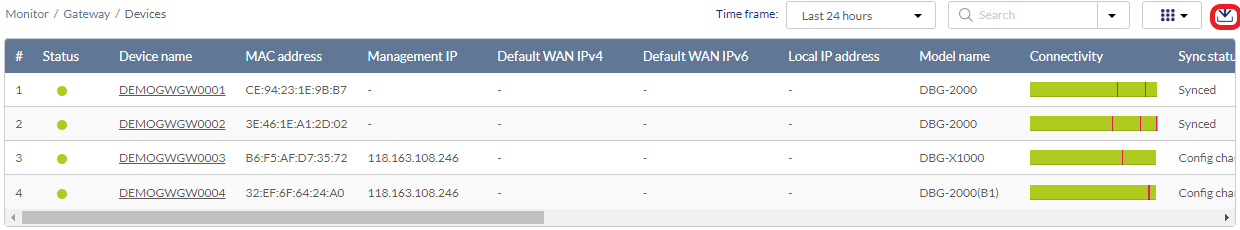
From the Devices window, you can consult a detailed log of events occurring on the network. You can also filter events using specific event filter parameters, including event type and time period.
The Device Monitor
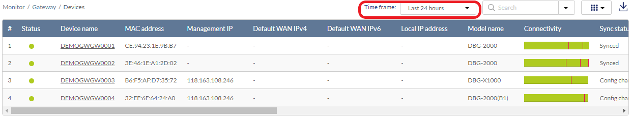
Customizing the Device Monitor Overview
- Navigate to Monitor > Gateway > Devices.
- Select a time frame from the drop-down menu to set the duration for connectivity information.
- Click the filter parameter icon.
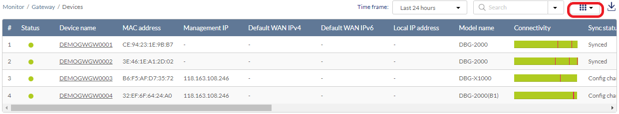
- Click the checkbox next to the parameters to display them in the overview.
Note: All checked parameters will automatically appear.
Downloading Device Monitoring Logs
- Navigate to Monitor > Gateway > Devices.
- From the device list, click the Download icon in the top-right to export the table listing as a CSV file.
Device Basic Settings
Changing the Device Site and Profile
- Navigate to Monitor >Gateway > Devices and select a device from the list.
- Select the Basic tab at the top.
- In the Site and Profile section, select a Site from the drop-down menu.
- In the Site and Profile section, select a Profile from the drop-down menu.
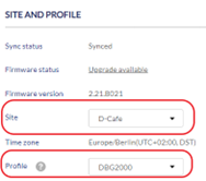
- Click Save.
The Performance Summary
Viewing and Customizing the Gateway Performance Summary
- Navigate to Monitor > Gateway > Devices and select a device from the list.
- Select the Summary tab. Click the tabs at the top to obtain additional information described below:
|
Status |
Provides connection information for the device along with basic port configuration and traffic statistics for each port. You can also obtain Internet usage for both download and upload data in a specified time frame. |
|
Statistics |
Provides reports of the number of connected clients in the selected time frame. You can also obtain reports of WAN port usage and the whole Internet usage as well as VPN usage. |
|
DHCP |
Provides the utilization rate of each configured DHCP subnet. It also lists the DHCP leases history. |
|
VPN Status |
Provides VPN connection statistics. The page lists the active VPN association or connections, the traffic details, and the tunnel state. You can view the status (connect or disconnect) of the gateway’s VPN connections as a whole (by selecting Overview for the Display VPN type) or view each VPN separately. |
Network Settings
Verifying and Changing the Default WAN Configuration
- Navigate to Monitor > Gateway > Devices and select a device from the list.
- Select the Network tab at the top.
- Under WAN Mode Configuration, verify the WAN mode and the primary WAN port (or Default WAN Configuration) settings. Note that the settings or configurations here depend on the device model and firmware.
To change the Default WAN or WAN Mode Configuration:
- Disable the option Use Profile configuration first at the top of the configuration page to allow changes.
- Select IPv4 and IPv6 default WAN configuration. Or select a WAN mode from the available options. For Primary WAN, designate a WAN port as the primary WAN. For Auto-rollover using WAN, select both Primary and Secondary WAN ports as well as the Health Check method. For DNS servers and Ping IP address methods, enter the respective server IP address as the destination to check the connectivity. Also enter the Retry interval (seconds) and Failover after (number of failed retries). For Load balancing, select the method (either Round robin or Spillover mode).
- For Round robin, configure the Health check method (or none) and enter the Retry interval (seconds) and Failover after (number of failed retries). Hence, if a WAN interface disconnects, only the alternate WAN ports will transfer traffic flows in a round robin manner. For Spillover, enter the Load tolerance (%) and Max bandwidth (Mbps) as the threshold value. Once the threshold is exceeded, new traffic flows will be allocated to the alternate WAN interfaces. The precedence for selection is based on the configuration of Primary, Secondary, and Tertiary WAN interface.
- Click Apply.
Note: The WAN mode can be configured using Profiles. Refer to Profiles of Configure - Gateway for more information on how to configure each section.
Using Dynamic DNS
- Navigate to Monitor > Gateway > Devices and select a device from the list.
- Select the Network tab at the top.
- Under Dynamic DNS, enable or disable the service.
- > Click Apply.
To add a DDNS service:
- Disable the option Use Profile configuration first at the top of the configuration page.
- Click Add. Enter the following information:
| WAN Interface | Select the WAN interface for configuration |
| Service Provider | Select the DDNS service provider. |
| Username/Password | Enter the DDNS account name and password. |
| Hostname | Enter the registered hostname with the DDNS service. |
| Wildcard | Enable or disable the wildcard option which will resolve *.hostname to the same designated IP address. |
| Use Public IP | Enable or disable the use of a public IP address. |
| Force Update Interval | Enter the DDNS update interval (days). |
- Click Save to close the screen. Then click Apply.
Using IP Alias for the WAN
Note: The IP Alias function is only available on supported models.
- Navigate to Monitor > Gateway > Devices and select a device from the list.
- Select the Network tab at the top.
- Under IP Aliasing , click Add to bind one or multiple IP addresses to a WAN interface.
Enter the following information:
WAN Interface Select the WAN interface for configuration IP Address/Subnet Mask Enter the IP address and subnet mask to bind to the WAN interface. - Click Save to close the screen. Then click Apply.
Viewing and Customizing the Gateway Port Status Overview
- Navigate to Monitor > Gateway > Devices and select a device from the list.
- Select the Summary tab at the top. The ports of the gateway device are displayed along with their detailed information shown in the table below:
|
Port Number |
Numbering of the ports on the connector panel. |
|
Interface Name |
The name that identifies the port. |
|
Port Status |
Displays the link state of the port. |
|
MAC Address |
The MAC address of the port. |
|
IP Address/Subnet Mask |
The IP address and subnet mask assigned to the port |
|
Gateway |
The gateway IP address if it has been assigned. |
|
DHCP Mode |
Displays if DHCP service has been enabled on the device. |
|
Sent Bytes |
The amount of data sent out of the port (bytes). |
|
Received Bytes |
The amount of data received through the port (bytes). |
|
Total Bytes |
The total amount of sent and received data volume (bytes). |
To configure a port's basic settings:
- Navigate to Monitor > Gateway > Devices and select a device from the list.
- Select the Network tab at the top.
- Disable Use Profile Configuration to allow modification.
- Under Port Configuration , select a port and click EDIT under Actions. Specify the following information for the selected LAN port:
|
Interface Type |
Select the connection type: LAN, WAN, or DMZ. |
|
Interface Name |
Enter a name to identify this interface. |
|
Bridge Network |
Enable or disable bridging with another network. Configure the interface with more settings below if bridging is not enabled. |
|
IP Address/Subnet Mask |
Enter an IP address with subnet mask. |
|
DHCP Mode |
Enable or disable DHCP service for IP address assignment. |
|
DHCP Server |
Enter the following information if DHCP server is selected. Domain name: Assign a domain name for DHCP service. Starting IP address/Ending IP address: Enter the range of IP addresses that can be assigned dynamically. Default gateway: Assign a default gateway for DHCP service. DNS server: Configure DNS by specifying a static DNS server, DNS setting from the ISP, or using DNS proxy. For static DNS, enter the DNS servers or WIN server IP address. Lease Time: Enter a time value of 1 to 10080 minutes. |
|
Allow Ping from LAN |
Enable or disable ping command executed from this port. |
|
DHCP Relay |
Enter the remote DHCP server address if DHCP relay is selected. |
|
DNS Proxy |
Enable or disable DNS proxy. |
For a WAN port (if the device supports this feature), configure the following:
|
Interface Type |
Select the connection type: LAN, WAN, or DMZ. |
|
Connection Type |
Select the connection method: DHCP, Static IP, PPPoE, PPTP, or L2TP. For Static IP, enter the IP address/Subnet mask, Gateway IP address and Primary/Secondary DNS servers, and specify whether to keep the original MAC address as well as the MTU size. For PPPoE, select the Address mode: Dynamic IP or Static IP. For static IP, enter the IP address/Subnet mask and PPPoE connection Username and Password. Then specify the Authentication type from one of the following: None, MS-CHAPv2, MS-CHAP, CHAP, PAP, or Auto-negotiate. For Dynamic IP, you don’t need to enter the IP address/subnet information but configure all other settings as specified above. For both addressing modes, enter the Service name (optional) and select the Reconnect mode: Always on, or On demand (enter the Maximum idle time to wait before terminating the connection in minutes for this option). Then configure the DNS servers and specify whether to keep the original MAC address as well as the MTU size. For PPTP, if Static IP is selected, enter the following IP address information: IP address/Subnet mask, Gateway IP address, and Static DNS IP address. For both Address modes, enter the PPTP server name and connection Username and Password. For both modes, configure whether MPPE (Microsoft Point-to-Point Encryption (MPPE) will be used and the Reconnect mode: Always on or On demand (enter the Maximum idle time to wait before terminating the connection in minutes for this option). Then configure the DNS servers and specify whether to keep the original MAC address as well as the MTU size. For L2TP, if Static IP is selected, enter the following IP address information: IP address/Subnet mask, Gateway IP address, and Static DNS IP address. For both Address modes, enter the L2TP server name and connection Username and Password. For both modes, enter the Secret (optional) and configure the Reconnect mode: Always on or On demand (enter the Maximum idle time to wait before terminating the connection in minutes for this option). Then configure the DNS servers and specify whether to keep the original MAC address as well as the MTU size. |
|
Advanced Settings |
Enable or disable the following passthroughs: Internet Protocol Security (IPsec) which is used for securing packets exchange at the IP layer. Point-to-Point Tunneling Protocol (PPTP) which is used for tunneling the Point-to-Point Protocol (PPP) communication in an IP network. Layer 2 Tunneling Protocol (L2TP) which is used for implementing Point-to-Point sessions utilizing multipoint tunneling technique. |
-
Click Save. Then click Apply to apply the settings to the affected device immediately.
Viewing and Configuring VLANs
VLANs allow you to divide the network to different segments. To obtain the current VLAN settings:
- Navigate to Monitor > Gateway > Devices and select a device from the list.
- Select Network > Addressing. The VLANs are displayed under the VLAN section with the following information:
|
Name |
A name that helps identify this VLAN. |
|
VLAN ID |
The assigned VLAN ID. |
|
Untagged/Tagged Ports |
The member ports for the untagged VLAN and tagged VLAN . |
|
IP address/Subnet Mask |
The IP address/Subnet mask configured for the VLAN. |
|
Captive Portal |
The associated Captive Portal page. |
To configure a VLAN:
- Disable the Use Profile configuration option.
- Under VLAN, click Add to add a new VLAN.
-
Click Apply at the top left to apply the changes to the affected device immediately.
Note: Local settings are configured identically to Profile settings. Refer to Profiles of Configure - Gateway for more information on how to configure each section.
Viewing and Configuring IP Management List
The IP Management list displays the IP assignment of the DHCP clients:
|
Host Name |
The host name of the client device. |
|
Interface |
The associated interface with the IP assignment. |
|
IP Address |
The assigned IP address of the host. |
|
MAC Address |
The MAC address of the host. |
|
IPv6 Suffix |
The assigned IPv6 suffix, which is the the last 64 bits of an IPv6 address. |
|
IP-MAC Binding |
Indicates whether the IP assignment is enforced on the client device with the specified MAC address to prevent the use of other static IP address on this client. |
|
DHCP IP Reservation |
Indicates whether this IP assignment is reserved for this client so that it can get the same IP assignment every time it sends a DHCP IP request. |
To configure IP management for DHCP clients:
- Disable the Use Profile configuration option.
- Under IP Management List, click Add to add a new IP assignment.
Note: Local settings are configured identically to Profile settings. Refer to Profiles of Configure - Gateway for more information on how to configure each section.
Viewing and Configuring Routing
Routing determines the path for packet delivery in a network. The routing capabilities vary depending on the device model.
To view the configured routing policies:
- Navigate to Monitor > Gateway > Devices and select a device from the list.
- Select Network > Routing. The configured routing protocols are displayed:
IPv4/IPv6 Static Route
|
Name |
A name that helps identify this route. |
|
Destination |
The destination subnetwork IP address. |
|
Subnet Mask |
The subnet mask of the destination address. This is only available for IPv4 configuration. |
|
Gateway |
The IP address of the gateway or next hop. |
|
Interface |
The associated interface for this route. |
|
Metric |
The number of hub count. |
|
Active |
Enable or disable this route configuration. |
IPv4/IPv6 Policy Route
|
Name |
The name that helps identify the route. |
|
Local Gateway |
The port of the device that the route would use. |
|
Protocol |
The protocols associated with this route. |
|
Source Network |
A single IP address or a range of IP addresses that this route will be applied to. “Any” means all source IP addresses. |
|
Destination Network |
A single IP address or a range of IP addresses that this route will be applied to. “Any” means all destination IP addresses. |
|
Source Port |
The port number used for this type of traffic. ”Any” means all source ports will be used for this service. |
|
Destination Port |
The port number used for this type of traffic. ”Any” means all destination ports will be used for this service. |
|
Active |
Enable or disable this route configuration. |
RIP Configuration
|
Interface |
The interface by which Routing Information Protocol (RIP) information exchange will be performed. |
|
Direction |
Indicates inbound, outbound, or traffic for both directions. |
|
Version |
The version of the RIP |
|
Authentication |
Indicates whether the authentication is enabled. |
|
Active |
Enable or disable this route configuration |
OSPFV2 Configuration
|
Interface |
The interface assigned to the area defined below. |
|
NSSA |
Enable or disable the not-so-stubby area (NSSA) which can import external route information. |
|
Area |
The assigned area ID. |
|
Priority |
The OSPF priority which is used for determining the OSPF designated router. |
|
Hello Interval |
The time interval (seconds) between each hello packet. |
|
Dead Interval |
The time (seconds) the device must wait before it declares a neighbor OSPF router down when a hello packet has not been received. |
|
Cost |
The cost of the OSPF path. |
|
Authentication |
Indicates the authentication method used |
|
LAN Route Exchange |
Enable or disable the exchange of LAN routing table. |
|
Active |
Enable or disable this OSPF route configuration. |
To configure routing policy:
- Disable the Use Profile configurationoption.
- Under each routing protocol supported by the device model, click Add to add a new routing policy.
Note: Local settings are configured identically to Profile settings. Refer to Profiles of Configure - Gateway for more information on how to configure each section.
Viewing and Configuring Services
Supported services can be configured individually depending on the features of the gateway.
To view and configure the supported services and network functions:
- Navigate to Monitor > Gateway > Devices and select a device from the list.
- Select the Network > Services.
Note: Local settings are configured identically to Profile settings. Refer to Profiles of Configure - Gateway for more information on how to configure each section.
Viewing and Managing Traffic
The Traffic Management provides control over certain types of traffic by setting limits on bandwidth and sessions. Note that the availability of this function depends on the capability of the gateway.
To view Traffic Shaping rules configured:
- Navigate to Monitor > Gateway > Devices and select a device from the list.
- Select Network > Traffic Management.
Under Traffic Shaping, the following is displayed:
|
Name |
The policy name. |
|
Policy Type |
Whether the traffic policy is applied to inbound or outbound traffic. |
|
WAN Interface |
The WAN port that this policy should be applied to. |
|
Management Type |
The metric to define the policy: Rate or Priority. Configure the following if Priority is selected: Low, Medium, or High. Higher priority means the traffic will be allocated with more bandwidth. If Rate is selected, enter the maximum bandwidth and minimum bandwidth (kbps). |
|
Priority/Bandwidth Rate |
The priority or the bandwidth configured for the respective management type. |
|
Service |
The type of traffic according to the protocol or application service configured. |
|
Traffic Selector Match Type |
The criteria for the traffic to which the policy should be applied: IP address, MAC address, or Interface. |
|
Schedule Policy |
The schedule policy that makes the policy effective during the designated time frame. Go to Configure > Schedule policies for scheduling information and configuration. |
Viewing and Managing Session Limiting
To view Session Limiting rules configured:
- Navigate to Monitor > Gateway > Devices and select a device from the list.
- Select Network > Traffic Management.
Under Session Limiting, the following is displayed:
|
Name |
The policy name. |
|
Source Type |
The source address can be configured as a single IP address, an IP address range, or an interface. |
|
Maximum Sessions |
The maximum number of sessions allowed (1-999). |
|
Schedule Policy |
The schedule policy that makes the policy effective during the designated time frame. Go to Configure > Schedule policies for scheduling information and configuration. |
Viewing and Managing Custom Warning Pages
To view Custom Warning Page configured:
- Navigate to Monitor > Gateway > Devices and select a device from the list.
- Select Network > Traffic Management.
Under Custom Warning Page, the following is displayed:
|
Name |
The policy name. |
|
Source Type |
The configured warning page to be displayed to users when the maximum limit of sessions has been reached . Go to Configure > Splash pages to view all the configured splash pages. |
|
Active |
Whether this rule is active or inactive. |
To configure Traffic Management:
- Navigate to Monitor > Gateway > Devices and select a device from the list.
- Select Network > Traffic Management.
- Disable the option Use Profile configuration.
Note: Local settings are configured identically to Profile settings. Refer to Profiles of Configure - Gateway for more information on how to configure each section.
Viewing and Configuring Captive Portal
The captive portal displays a splash page to wireless users who are required to agree to terms and conditions to use Internet services.
To view Captive Portal configured:
- Navigate to Monitor > Gateway > Devices and select a device from the list.
- Select Network > Captive Portal.
The following information is displayed:
|
Name |
The profile name. |
|
Captive Portal |
The authentication method for the users. |
|
Splash Page |
The pre-configured splash page which a wireless user must visit prior to using Internet services. The design of the page depends on the use case. |
|
Basic Login |
For basic login page, the associated authentication method: a local authentication database or an authentication server system. |
|
3rd party Credentials |
The configured third-party credential to be used for login. |
|
SSID/VLANs |
A pre-configured SSID/VLAN assigned to this captive portal setting. |
To configure Captive Portal:
- Navigate to Monitor > Gateway > Devices and select a device from the list.
- Select Network > Captive Portal.
- Disable the option Use Profile configuration.
Note: Local settings are configured identically to Profile settings. Refer to Profiles of Configure - Gateway for more information on how to configure each section.
Viewing and Configuring High Availability
Virtual Router Redundancy Protocol (VRRP) can be utilized to implement fault tolerance and load balancing on a network by designating primary and backup roles among the virtual routers. The primary router is responsible for processing packets sent to a virtual IP address and the backup router takes up the primary role when the primary becomes unavailable. This availability of this feature depends on device model.
To view VRRP settings configured:
- Navigate to Monitor > Gateway > Devices and select a device from the list.
- Select Network > High Availability. The following is displayed:
|
VRRP ID |
The unique identifier for the VRRP group. |
|
Interface |
The interface to which the VRRP configuration would be applied. |
|
IP Address |
The virtual IP address. |
|
Node Type |
The designated role of the virtual router: Master or Backup. |
|
Priority |
The Priority determines the order of selection for a primary virtual router among the backup virtual routers (1-255). Higher number means high priority. |
To configure VRRP settings:
- Navigate to Monitor > Gateway > Devices and select a device from the list.
- Select Network > High Availability.
- Disable the option Use Profile configuration.
Note: Local settings are configured identically to Profile settings. Refer to Profiles of Configure - Gateway for more information on how to configure each section.
Viewing and Configuring Wireless
You can create multiple SSIDs for your wireless network and configure each SSID with unique settings to accommodate different wireless usage scenarios. You can also configure radio settings such as operating mode and channels for different frequencies supported for the device model. Note that this feature is only available for supported models.
Note: Local settings are configured identically to Profile settings. Refer to Profiles of Configure - Gateway for more information on how to configure each section.
Security Settings
Security features consist of firewall, intrusion prevention, and web content filtering as well as application control.
Note: Changing the Routing mode from Network Address Translation (NAT) to Router (go to Network > Addressing), the Security Firewall’s option of Use Profile configuration will be disabled. Moreover, the rules configured for Port forwarding, Port triggering, and 1:1 NAT will be erased.
Firewall
To view a gateway's firewall settings:
- Navigate to Monitor > Gateway > Devices and select a device from the list.
- Select Security > Firewall.
The following information is displayed:
IPV4/IPv6 FIREWALL RULES
IPv4/Ipv6 Firewall Rules allow or block certain types of traffic that need to be forwarded through the device.
|
Priority |
The assigned priority number (1-998). Lower number means higher priority. |
|
Name |
The name of the rule. |
|
Policy |
Indicates whether it is a allow or deny rule. |
|
Protocol |
The associated protocol for the rule: Any, TCP, UDP, TCP/UDP, or ICMP. |
|
Source Interface |
The interface that the traffic is sent from. |
|
Source |
A single IP address or a range of IP addresses as the source host. Any means traffic from all IP addresses. |
|
Source Port |
The source port number used for this type of traffic. Any means all ports. |
|
Destination |
A single IP address or a range of IP addresses as the destination host. Any means traffic destined to all IP addresses. |
|
Destination Port |
The destination port number used for this type of traffic. Any means all ports. |
|
Schedule |
The associated Schedule Policy. |
|
Active |
Indicates whether this rule is enabled or disabled. |
Note: The availability of IPv6 Firewall Settings depends on the features of the device model.
Port Forwarding
Port Forwarding redirects traffic entering the WAN to another port on the LAN. This is useful when a certain service is hosted on an interval server on the LAN.
To view Port Forwarding rules:
- Navigate to Monitor > Gateway > Devices and select a device from the list.
- Select Security > Firewall.
The following information is displayed:
|
Name |
The name for the rule. |
|
Mode |
Indicates whether the rule is for traffic forwarding or port translation. |
|
Interface |
The WAN interface to which this rule should be applied. |
|
Protocol |
The associated protocol of this rule: TCP, UDP, or TCP/UDP. |
|
Public Port |
The external port associated with this type of traffic or service (1-65535). It can be a single port or a range of ports. |
|
Local IP |
The IP address of the local server. |
|
Local Port |
The local port used for this service if translation mode is selected. |
|
Allowed Remote IPs |
The IP addresses of the remote hosts that this rule will be applied to. Any means all remote hosts. |
|
Active |
Indicates whether this rule is enabled or disabled. |
Port Triggering
Port Triggering dynamically opens public ports for inbound traffic after certain ports are triggered by a service request.
To view Port Triggering rules:
- Navigate to Monitor > Gateway > Devices and select a device from the list.
- Select Security > Firewall.
The following information is displayed:
|
Name |
The rule's name. |
|
Protocol |
The protocol to which the rule is applied: TCP, UDP, or TCP/UDP. |
|
Outgoing Trigger Port |
The outgoing port used for this service. |
|
Incoming Trigger Port |
The incoming port used for this service. |
|
Active |
Indicates whether this rule is enabled or disabled. |
1:1 NAT
One-to-one NAT allows a static mapping between an internal IP address and an external IP address.
To configure 1:1 NAT rules:
- Navigate to Monitor > Gateway > Devices and select a device from the list.
- Select Security > Firewall.
The following information is displayed:
Name
The rule name.
Interface
The WAN interface that this rule should be applied to.
WAN IP
The WAN IP address as the external IP address for translation.
Local IP
The local IP address as the interval IP address for translation.
Protocol
Indicates the associated protocol of this rule: TCP, UDP, or TCP/UDP.
Port
The port used for this traffic type.
Allowed remote IPs
The IP addresses of the remote hosts that this rule will be applied to. Any means to allow all remote hosts.
To configure Firewall rules:
- Navigate to Monitor > Gateway > Devices and select a device from the list.
- Select Security > Firewall.
- Disable the option Use Profile configuration.
Note: Local settings are configured identically to Profile settings. Refer to Profiles of Configure - Gateway for more information on how to configure each section.
Viewing and Configuring IPS Settings
To view Intrusion detection and prevention settings:
- Navigate to Monitor > Gateway > Devices and select a device from the list.
- Select Security >IPS.
- Disable the option Use Profile configuration.
If the device is equipped of intrusion detection functions, you can enable or disable the following services:
|
Intrusion Detection |
Enable intrusion detection. And select the WAN and LAN interfaces that the IPS and IDS should be implemented. |
|
Intrusion Prevention |
Enable intrusion prevention. And select the WAN and LAN interfaces that the IPS and IDS should be implemented. |
|
Stealth Mode |
This mode protects your device from Internet intrusion by not responding to unauthorized requests. |
|
Block TCP Flood |
Enable to block TCP flooding to WAN. |
|
Bock UDP Flood |
Enable to block UDP flooding to LAN. |
|
Filter Check Mode |
Enable the TCP filtering check mode. |
|
Allow ICMP Traffic |
Enable to allow packets of Internet Control Message Protocol to pass through. |
|
DoS Attacks |
Denial-of-Service (DoS) attacks encompass SYN Flood, ICMP Flood, and Echo storm. Configure the flood rate of each attack in packets/second for detection. |
- Click Apply at the top left to apply the settings to the affected devices immediately.
Viewing and Configuring Web Content Filter
The Web Content Filter is used to prevent access to unwanted websites. It allows you to create profiles that can take effective during the designated time frame and block websites belonging to a certain category.
Web Content Filter List
To view the Web Content Filter List:
- Navigate to Monitor > Gateway > Devices and select a device from the list.
- Select Security >Web Content Filter.
Under Web Content Filter List, the following is displayed:
|
Name |
The name for the filtering rule. |
|
Policy |
State whether this is a allow or block policy. |
|
Schedule |
The pre-configured scheduling. |
|
Scope |
The specified hosts or the whole network that this rule will be applied to. |
|
Filtering Type |
The type consists of a variety of categories, URLs, and custom groups to restrict the access to defined websites. |
|
Active |
State whether the rule is active. |
Under Custom Warning Page, you can obtain the configured warning page that will display related messages when a restricted webpage is being visited. The following is displayed:
|
Name |
Enter a name for this configuration. |
|
Source Type |
The pre-defined warning page to be displayed. |
|
Actions |
State whether the rule is active. |
Under Custom Group List, you can obtain the Custom group which will be used to define the content filtering type above:
|
Group Name |
The name for the custom group. |
|
URLs |
If URL filtering is used, it shows the name and keyword for the website. This blocks access to websites based on a website's domain name (e.g. google.com) and keywords with matching URLs. For example, keyword "ABC" will block "www.ABC.com" and "xxx.ABC.com" and other URLs containing ABC. |
|
Category Filtering |
If Category filtering is used, it shows the pre-defined categories to block access to. |
|
In Use |
State whether this rule has been activated. |
To configure Firewall rules:
- Navigate to Monitor > Gateway > Devices and select a device from the list.
- Select Security > Web Content Filter.
- Disable the option Use Profile configuration.
Note: Local settings are configured identically to Profile settings. Refer to Profiles of Configure - Gateway for more information on how to configure each section.
Viewing and Configuring Application Control
The Application Control is used to restrict certain communication of applications. It allows you to create profiles that can take effective during the designated time frame and prevent traffic of certain applications from being transferred.
Auto Upgrade
Enable automatic upgrade of application signature database and select the update schedule by entering the upgrade frequency in minutes or setting a specified time of a designated weekday for weekly updates.
To add an application control rule:
- Navigate to Monitor > Gateway > Devices and select a device from the list.
- Select Security > Application Control.
- Under Application Control List, the following information is displayed:
|
Name |
The policy name. |
|
Policy |
State whether this is a allow or block policy. |
|
Schedule |
The pre-configured schedule. For configured scheduling methods, go to Configure > Schedule policies. |
|
Scope |
The specified hosts or the whole network that this rule will be applied to. |
|
Application |
State whether the filtering rule is based on a single application, or a single application from a pre-defined category, or a custom group of selected applications. |
|
Active |
State whether the application control policy is active or inactive. |
Under Custom Group List, you can obtain Custom Group defined which will be used to define the application type above:
|
Group Name |
The name of the custom group. |
|
Application List |
The selected applications for the custom group. |
|
In Use |
State whether this rule has been activated. |
To configure Application Control:
- Navigate to Monitor > Gateway > Devices and select a device from the list.
- Select Security > Application Control.
- Disable the option Use Profile configuration.
Note: Local settings are configured identically to Profile settings. Refer to Profiles of Configure - Gateway for more information on how to configure each section.
VPN Settings
A Virtual Private Network (VPN) builds an encrypted connection between endpoints over a public network utilizing tunneling techniques. VPN can be configured only if your device supports this feature.
Site to Site VPN
The site-to-site VPN is a technique that allows connectivity between the offices located at multiple locations by setting up an IPsec tunnel over the Internet to access the intranet. In short, a site-to-site VPN builds a secure path over an insecure path. The Nuclias cloud gateway allows users to establish a VPN tunnel without manually entering the tunnel endpoint details and the local/remote networks. Instead, the Nuclias cloud gateway maintains these details and lets users select the networks.
Configuring Quick VPN
Quick VPN is a Nuclias auto-provisioning site-to-site VPN technology that allows you to quickly and easily build VPN tunnels between Nuclias gateway devices without tedious manual VPN configuration. If it is disabled, set up VPN manually at Manual VPN Settings to establish VPN connection with other partners.
To view or configure Quick VPN settings:
- Navigate to Monitor > Gateway > Devices and select a device from the list.
- Select VPN > Site-to-site VPN.s
- Select the topology: Hub-and-Spoke or Full Mesh. If Full Mesh is selected, the VPN establishes the Gateway-to-Gateway IPsec tunnel with other devices registered in the same or different sites of the same organization. To establish a tunnel with a particular remote device, enable the Join member field in the Remote VPN participants table. Once the tunnel configuration is pushed to the remote peers, traffic gets initiated by the user, and a tunnel is established between the remote peers.
- If Hub-and-Spoke is selected, specify the role to be either a hub or spoke. If Spoke is selected, you can choose hubs to build VPN tunnels in the Exist hubs table. In addition, it lists the Exist hub devices available with the option of Primary Hub. If you enable the Primary Hub field, the selected hub will be the primary hub for the spoke and can communicate to all the spoke devices linked to this hub. At a time, you can enable only one primary hub. If Hub is selected, then VPN tunnels will be built among hubs and dependent spokes.
- If Hub mode is selected, enable or disable VPN connection with a remote peer. You may also choose to designate a remote peer as a backup hub.
- If Spoke mode is selected, you can choose to designate a remote peer as the primary hub.
- Click Apply.
Quick VPN Settings
In the Local networks section, if you have multiple subnets, you can specify which one subnet participates in the VPN, i.e., traffic from the enabled subnet will be encrypted by the IPsec VPN. All local subnets must be unique within the VPN topology
Note: A list of Quick VPN connections will be displayed in the Summary > VPN Status page. Select Quick VPN (Full Mesh and Hub-and-Spoke) as the Display VPN type.
Configuring Manual VPN
To view or configure Manual VPN settings:
- Navigate to Monitor > Gateway > Devices and select a device from the list.
- Select VPN > Site-to-site VPN. Enter the following:
|
Connection Name |
Enter a name for this VPN connection (1-64 characters). |
|
IKE Profile |
Select the IKE profile which contains security settings that will be used for the VPN connection. |
|
Local Network |
The scope of the local network to which the VPN connection will apply. |
|
Local Network |
Enter a local IP address or subnetwork of the local network to participate in the VPN. If Single IP is selected, enter the IP address. If Subnet is selected, enter the IP address and subnet mask (or prefix for IPv6). Select Any for the entire local network. |
|
Remote Network |
Enter a remote IP address or subnetwork of the remote network to participate in the VPN. If Single IP is selected, enter the IP address. If Subnet is selected, enter the IP address and subnet mask (or prefix for IPv6). Select Any for the entire remote network. |
|
Outgoing Interface |
Select an interface to which the VPN connection will use. |
|
Remote Gateway |
Select FQDN or Static IP for configuring the remote gateway address. Then enter the IP address or FQDN address. |
|
Keep-alive |
Enable or disable keep-alive for VPN reconnection. If enabled, enter the source and destination IP address as well as the detection period in seconds (10-199) and retry after the number of failures (3-99). |
|
Idle Timeout |
Enter the maximum length of time that the VPN connection can stay active when three is no traffic. |
|
Dead Peer Detection |
Enable detection for dead peers. If enabled, enter the detection interval (10-999 seconds) and Retry after failure (3-99 times). |
|
NetBIOS Broadcast |
Enable or disable NetBIOS broadcast from one end to be forwarded to the other end of the VPN connection. |
|
Outgoing Backup Interface |
Select an interface to which the VPN connection will use as a backup if Dead Peer Detection is enabled. |
|
Remote Backup Gateway |
Select FQDN or Static IP for configuring the remote gateway address if Dead Peer Detection is enabled. |
|
IKE Backup Profile |
Select the IKE profile which contains security settings that will be used for the backup VPN connection if Dead Peer Detection is enabled. |
To add an IKE profile,enter the following:
|
Profile Name |
Enter a name for this IKE profile. |
|
IKE Version |
Select the IKE version: v1 or v2. |
|
IKE phase-1 Settings |
|
|
Exchange Mode |
Select the exchange mode: Aggressive or Main. |
|
Local Identifier Type |
Select the identification method: Local WAN IP, FQDN, or User-FQDN. And enter the identifier according to the selected method. |
|
Remote Identifier Type |
Select the identification method: Remote WAN IP, FQDN, or User-FQDN. And enter the identifier according to the selected method. |
|
DH Group |
Select a Diffie-Hellman (DH) Group for key exchange. These groups vary in prime key lengths. |
|
Encryption Algorithm |
Select encryption algorithm(s) for ESP packets encryption. |
|
Authentication Algorithm |
Select authentication algorithm(s). And enter the SA lifetime in seconds (300-604800). |
|
Authentication Method |
Select the authentication method. Then enter the preshared key or select a certificate depending on the method selected. Go to Settings > Certificate Management for Certificate list. |
|
Extended Authentication |
Enable this and select extended authentication method: Authentication server, IPsec host, or Local authentication. Depending on the method, select the corresponding RADIUS/LDAP/POP3/Active Directory/NT Domain server or Local Authentication profile or enter the username and password for IPsec host. Refer to Configure > Authentication > Local Authentication list and Authentication servers for Authentication profiles and servers. |
|
IKE phase-2 Settings |
|
|
Protocol Selection |
Select either ESP or AH. If Encapsulating Security Payload (ESP) is selected, select the Encryption algorithm to encrypt or decrypt ESP packets. |
|
Authentication Algorithm |
Select the authentication algorithm for header packets validation. |
|
SA Lifetime (sec.) |
Enter the SA lifetime (300-604800 seconds) for the active duration of a VPN tunnel. |
|
Perfect Forward Secrecy |
Enable or disable the Perfect Forward Secrecy. If enabled, the VPN communication is better protected with renewed negotiation of key values in the exchange. |
|
DH Group |
If the above PFS is enabled, select the DH group for key establishment. |
- Click Apply at the top.
Note: A list of Quick VPN connections will be displayed in the Summary > VPN Status page. Select Quick VPN (Manual) as the Display VPN type.
Client to Site VPN
An IPsec policy can be defined between this router and another gateway to create network-to-network IPsec tunnels. To configure IPsec VPN Server settings:
- Navigate to Monitor > Gateway > Devices and select a device from the list.
- Select VPN > Client-to-site VPN. Enter the following:
|
Connection Name |
Enter a name for this configuration |
|
IKE |
Select a pre-configured IKE profile for this VPN configuration. |
|
Local Network |
Enter the IP address and subnet mask of the local network. Select Any to not restrict to a single subnet. |
|
Tunnel Mode |
Select either full or split tunnel for the mode. Select Full tunnel or Split tunnel. The Split mode will split DNS requests among DNS servers. It allows you to create two zones for the same domain, one to be used by the internal network, the other used by the external network .For Split tunnel, enter the Split Domain names. |
|
DHCP Relay |
Enable or disable DHCP relay. If enabled, enter the IP address of the relay gateway. If disabled, enter the following IP address information. |
|
Starting IP Address/Ending IP Address |
Enter the range of the IP addresses for VPN connections. |
|
Primary/Secondary DNS |
Enter the primary and optional secondary DNS servers. |
|
Primary WINS Server/Secondary WINS Server |
Enter the primary and optional secondary Windows Internet Naming Service (WINS) servers. |
|
Outgoing Interface |
Select the WAN interface to which the IPsec VPN should apply. |
|
Split DNS |
Enable or disable Split DNS if Split tunnel is selected. And enter the domain names if enabled (3-253 characters). |
|
NetBIOS Broadcast |
Enable or disable NetBIOS information to be forwarded to the other endpoint of the VPN tunnel. The information is used for name resolution in Windows networking. |
To add an IKE profile, enter the following:
|
Profile Name |
Enter a name for this IKE profile. |
|
IKE Version |
Select the IKE version: v1 or v2. |
|
IKE phase-1 Settings |
|
|
Exchange Mode |
Select the exchange mode: Aggressive or Main. |
|
Local Identifier Type |
Select the identification method: Local WAN IP, FQDN, or User-FQDN. And enter the identifier according to the selected method. |
|
Remote Identifier Type |
Select the identification method: Remote WAN IP, FQDN, or User-FQDN. And enter the identifier according to the selected method. |
|
DH Group |
Select a Diffie-Hellman (DH) Group for key exchange. These groups vary in prime key lengths. |
|
Encryption Algorithm |
Select encryption algorithm(s) for ESP packets encryption. |
|
Authentication Algorithm |
Select authentication algorithm(s). And enter the SA lifetime in seconds (300-604800). |
|
Authentication Method |
Select the authentication method. Then enter the preshared key or select a certificate depending on the method selected. Go to Settings > Certificate Management for Certificate list (refer to Certificate Management) . |
|
Extended Authentication |
Enable this and select extended authentication method: Authentication server, IPsec host, or Local authentication. Depending on the method, select the corresponding RADIUS/LDAP/POP3/Active Directory/NT Domain server or Local Authentication profile or enter the username and password for IPsec host. Refer to Configure > Authentication > Local Authentication list and Authentication servers for Authentication profiles and servers. |
|
IKE phase-2 Settings |
|
|
Protocol Selection |
Select either ESP or AH. If Encapsulating Security Payload (ESP) is selected, select the Encryption algorithm to encrypt or decrypt ESP packets. |
|
Authentication Algorithm |
Select the authentication algorithm for header packets validation. |
|
SA Lifetime (sec.) |
Enter the SA lifetime (300-604800 seconds) for the active duration of a VPN tunnel. |
|
Perfect Forward Secrecy |
Enable or disable the Perfect Forward Secrecy. If enabled, the VPN communication is better protected with renewed negotiation of key values in the exchange. |
|
DH Group |
If the above PFS is enabled, select the DH group for key establishment. |
- Click Apply at the top.
PPTP/L2TP
A PPTP server is available on the router for LAN and WAN PPTP client users to access.
To configure PPTP/L2TP Server settings
- Navigate to Monitor > Gateway > Devices and select a device from the list.
- Select VPN > PPTP/L2TP. Enter the following:
|
Name |
Enter a name for the configuration profile of the server (1-64 characters). |
|
Server Type |
Select either PPTP or L2TP. |
|
Routing Mode |
Select either NAT or Router. |
|
Starting IP Address/Ending IP Address |
Enter the LAN IP address range to be assigned to the VPN clients. |
|
Authentication Server |
Select the authentication server. Depending on the method, select the corresponding RADIUS/LDAP/POP3/Active Directory/NT Domain server or Local Authentication profile. Go to Configure > Authentication > Local Authentication list and Authentication Servers for Local authentication profiles and authentication servers list. |
|
Authentication Protocol |
Select the authentication protocol(s): All, PAP, CHAP, MS-CHAP, and MS-CHAPv2. |
|
Encryption |
[PPTP only] Select the encryption method(s) for PPTP: For PPTP, select All, MPPE 40 bit, MPPE 128 bit, or Stateful MPPE. The Microsoft Point-to-Point (MPPE) encrypts data for PPTP VPN. |
|
Idle Timeout |
The length of time (seconds) to wait before terminating a VPN session (300-1800). |
|
NetBIOS |
[PPTP only] Enable or disable NetBIOS, which is used for name resolution in Windows networking, if there is a WINS server set up in your LAN. If enabled, enter the Windows Internet Naming Service (WINS) server IP address. This option is only available for PPTP. |
|
Enable Secret Key |
[L2TP only] Enable or disable the secret key (or preshared key) with 8-63 characters which will be required for client VPN settings. |
|
L2TP over IPsec |
[L2TP only] Enable or disable L2TP over Internet Protocol Security (IPsec), on which L2TP relies for secure packets exchange. |
| IKE Version: Configure Internet Key Exchange (IKE) if L2TP Over IPsec is enabled. | |
|
IKE version |
Select the IKE version for configuration. |
| IKE phase-1 settings | |
|
Exchange Mode |
Select the exchange mode: Aggressive or Main. |
|
Local Identifier Type |
Select the identification method: Local WAN IP or FQDN. And enter the identifier according to the selected method. |
|
Remote Identifier Type |
Select the identification method: Remote WAN IP or FQDN. And enter the identifier according to the selected method. |
|
DH Group |
Select a Diffie-Hellman (DH) Group for key exchange. These groups vary in prime key lengths. |
|
Encryption Algorithm |
Select encryption algorithm(s) for ESP packets encryption. |
|
Authentication Algorithm |
Select authentication algorithm(s). And enter the SA lifetime in seconds (300-604800). |
|
Authentication Method |
Select the authentication method. Then enter the preshared key or select a certificate depending on the method selected. Go to Settings > Certificate Management for Certificate list. |
|
Extended Authentication |
Enable this and select extended authentication method: Authentication server, IPsec host, or Local authentication. Depending on the method, select the corresponding RADIUS/LDAP/POP3/Active Directory/NT Domain server or Local Authentication profile or enter the username and password for IPsec host. Refer to Configure > Authentication > Local Authentication list and Authentication servers for Local authentication profiles and authentication servers. |
| IKE phase-2 settings | |
|
Protocol Selection |
Select either ESP or AH. If Encapsulating Security Payload (ESP) is selected, select the Encryption algorithm to encrypt or decrypt ESP packets. |
|
Authentication Algorithm |
Select the authentication algorithm for header packets validation. |
|
SA Lifetime (sec.) |
Enter the SA lifetime (300-604800 seconds) for the active duration of a VPN tunnel. |
|
Perfect Forward Secrecy |
Enable or disable the Perfect Forward Secrecy. If enabled, the VPN communication is better protected with renewed negotiation of key values in the exchange. |
|
DH Group |
If the above PFS is enabled, select the DH group for key establishment. |
PPTP VPN Client can be configured on this router to access a remote network.
To configure a VPN client,enter the following:
|
Name |
Enter a name for the PPTP/L2TP configuration profile of the client (1-64 characters). |
|
Client Type |
Select either PPTP or L2TP. |
|
VPN Server |
Enter the IP address or FQDN of the VPN server |
|
Tunnel Type |
Select Full tunnel or Split tunnel. Split tunnel mode only sends traffic to the private LAN with pre-specified client routes and give the client access to specific private networks, thereby allowing access control over specific LAN services. |
|
Remote Network/Netmask |
Enter the remote network and netmask if split tunnel is selected. |
|
Username/Password |
Enter the username and password required for connection. |
|
Encryption |
For L2TP server, enter the Secret key (8-63 characters) if encryption is enabled. This value must match the preshared key value entered on the VPN server. |
|
MPPE |
Enable the Microsoft Point-to-Point Encryption (MPPE), which encrypts data for VPN communication. |
|
Idle Timeout |
For PPTP, enter the length of time (seconds) to wait before terminating a session. |
|
Reconnect Mode |
For L2TP, select On demand or Always on. Enter the Maximum idle time in seconds (300-1800) to wait before dropping an idle connection. |
|
L2TP over IPsec |
Enable or disable L2TP over Internet Protocol Security (IPsec), on which L2TP relies for secure packets exchange. |
| IKE Version: Configure Internet Key Exchange (IKE) if L2TP Over IPsec is enabled. | |
|
IKE version |
Select the IKE version for configuration. |
| IKE phase-1 settings | |
|
Exchange Mode |
Select the exchange mode: Aggressive or Main. |
|
Local Identifier Type |
Select the identification method: Local WAN IP or FQDN. And enter the identifier according to the selected method. |
|
Remote Identifier Type |
Select the identification method: Remote WAN IP or FQDN. And enter the identifier according to the selected method. |
|
DH Group |
Select a Diffie-Hellman (DH) Group for key exchange. These groups vary in prime key lengths. |
|
Encryption Algorithm |
Select encryption algorithm(s) for ESP packets encryption. |
|
Authentication Algorithm |
Select authentication algorithm(s). And enter the SA lifetime in seconds (300-604800). |
|
Authentication Method |
Select the authentication method. Then enter the preshared key or select a certificate depending on the method selected. Go to Settings > Certificate Management for Certificate list. |
|
Extended Authentication |
Enable this and select extended authentication method. Enter the Username and Password if IPsec host is selected. |
| IKE phase-2 settings | |
|
Protocol Selection |
Select either ESP or AH. If Encapsulating Security Payload (ESP) is selected, select the Encryption algorithm to encrypt or decrypt ESP packets. |
|
Authentication Algorithm |
Select the authentication algorithm for header packets validation. |
|
SA Lifetime (sec.) |
Enter the SA lifetime (300-604800 seconds) for the active duration of a VPN tunnel. |
|
Perfect Forward Secrecy |
Enable or disable the Perfect Forward Secrecy. If enabled, the VPN communication is better protected with renewed negotiation of key values in the exchange. |
|
DH Group |
If the above PFS is enabled, select the DH group for key establishment. |
- Click Save.
Note: A list of PPTP/L2TP connections will be displayed in the Summary > VPN Status page.
OpenVPN
OpenVPN allows peers to authenticate each other using certificates, or username/password. When used in a multiclient-server configuration, it allows the server to release an authentication certificate for every client, using signature and Certificate authority. An OpenVPN can be established through this router.
To configure OpenVPN settings
- Navigate to Monitor > Gateway > Devices and select a device from the list.
- Select VPN > OpenVPN. Enter the following:
|
Mode |
Select the mode for the OpenVPN: Server, Client, or Access server client. |
|
Upload Access Server Client |
[Access Server Client mode only] Upload a configuration file which contains server and client IP address information if Access server client mode is selected. In access server client mode, the user has to download the auto login profile from the OpenVPN Access Server and upload the same to connect. |
|
CRL Certificate |
[Access Server Client mode only] Openvpn provides CRL authentication using CRL certificate. You can upload the required certificates by enabling it it first. |
|
VPN Network/Netmask |
[Server mode only] Enter the network IP address/netmask of the VPN. This is only available for the Server mode. |
|
Server IP/Failover Server IP |
The IP address or FQDN of the VPN server and failover server. This is only available for the Client mode. |
|
Duplicate CN |
[Server mode only] Enable or disable the duplicate CN to allow or disallow the same certification for multiple clients. This is only available for the Server mode. |
|
Port |
Enter the port number for VPN communication. The default is 1194. |
|
Tunnel Protocol |
Select the protocol for tunneling: TCP or UDP. |
|
Encryption Algorithm |
Select the encryption method: AES-128, BF-CBC, AES-192, or AES-256. |
|
Hash Algorithm |
Select the hash algorithm: SHA1, SHA256, or SHA512. |
|
Tunnel Type |
[Server mode only] Select the tunnel type: Full or Split. If Split is selected, enable or disable the client-to-client communication. Full Tunnel mode sends all traffic from the client across the VPN tunnel to the router. Split Tunnel mode only sends traffic to the private LAN with specified client routes. This is only available for Server mode configuration. |
|
User-based Authentication |
Enable or disable user-based authentication. If this is enabled, select the user profiles for Local authentication if server mode is used (refer to Local Authentication). If client mode is used, enter the username and password for VPN connection. Also select a certificate for TLS key if TLS authentication is used (refer to Certificate Management). |
|
Certificate Verification |
Enable or disable the use of certificate for verification. |
|
Certificate |
Select an available certificate from the list. The content of the certificate will be loaded in the field below. |
|
TLS Authentication Key |
Enable or disable the TLS authentication. If enabled, select an TLS authentication key from the certificate list. To obtain the certificate list, go to Settings > Certificate Management. |
|
DH Key |
Select a DH key from the certificate list. This is only available for Server mode configuration. To obtain certificate list, go to Settings > Certificate Management |
|
Server Policies |
Enable or disable the server policy. Enter the server policy and add a new server policy to permit or block networks for VPN connections. These policies can be applied to a specific IP address or IP networks on the LAN and can be enforced on the specified scope according to the supported features of the router. The List of Available Policies can be filtered based on whether it applies to a user, group, or all users (global). To add a new server policy, enter the following: Policy name: Give a name for this policy. Policy: Select whether it is a Deny or Permit policy. Scope: Select whether it is a global policy or to be applied for certain users using Local authentication. Select the user profile if Local authentication is selected. Apply policy to: Select whether to apply this policy to a single IP address or a subnet work and enter the required IP address and/or the Subnet mask and the port number. ICMP: enable or disable Internet Control Message Protocol (ICMP) traffic in VPN connections. |
|
Remote Networks |
If this is enabled, click Add to add a remote network configuration: enter a name for the configuration and the remote network IP address and subnet mask. |
|
Port |
Enter the port number (1-65535). This can be a single port or a range of ports, e.g. 3000-3200. |
|
ICMP |
Enable or disable the use of ICMP in the VPN communication. |
OpenVPN provides authentication using certificates. This system will allow you to configure client list using Local Authentication list (refer to Local Authentication) and centrally manage the client certificates (refer to Certificate Management).To configure Client list for Server mode configuration:
- Under Client list, click Import. The Import users from local authentication list page displays.
- Select a pre-configured local user profile or click Add local authentication and configure a local user profile by specifying the following: the Local Authentication profile name, the Access level, Managed Sites, and the username and password for each new user. You can use the Bulk import function to upload a CSV file containing the user information to add multiple users at once. Refer to Configure > Authentication > Local Authentication list for more information.
- Click Save. Once a Local authentication profile is imported successfully, you can manage the clients' certificates in the Certificate Management page (go to Settings > Certificate management) .
To configure OmniSSL Portal Layout for Server mode configuration:
OmniSSL facilitates the client installation from the device via the instructions on the portal page and is an enhancement to the existing OpenVPN. The enhancements allow the VPN tool to be used via mobile devices and eliminate browser and Java dependencies.
- Under OmniSSL Portal Layout, click Add. The Add portal layout configuration page displays.
- Enter a name for the profile and select a pre-defined login page for OmniSSL. Refer to Configure > Splash pages for more information. The Splash pages allow you to create a custom page that is presented upon authentication to the remote OmniSSL users.
- Click Save.
Note: A list of OpenVPN connections will be displayed in the Summary > VPN Status page.
GRE Tunnel
GRE tunnels allow for broadcast traffic on the LAN of the router to be passed over the internet and received by remote LAN hosts.
To view or configure GRE Tunnel settings:
- Navigate to Monitor > Gateway > Devices and select a device from the list.
- Select VPN > GRE Tunnel. Enter the following:
|
Name |
The name for the GRE Tunnel configuration. |
|
Interface |
Select the WAN interface to create this tunnel with from the drop-down menu. |
|
GRE Tunnel IP/Subnet Mask |
Enter the IP address/subnet mask of this endpoint. It will be referenced in the other router's static route as the Gateway IP address.
|
|
Remote IP |
Enter the WAN IP address of the endpoint router.
|
|
Static Route Configuration |
IP address/Subnet mask: Enter the destination IP address/subnet mask of the static route from the remote LAN subnet. Gateway IP address: Enter the GRE tunnel IP of the terminating router that manages the remote LAN. |
- Click Save.
- Click Apply at the top left to apply the settings to the affected device immediately.
Note: The GRE connection status will be displayed in the Summary > VPN Status page.
Tools
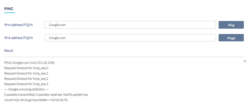
Performing a Device Ping Test
- Navigate to Monitor > Gateway > Devices and select a device from the list.
- Select the Tools tab in the top-right of the screen.
- In the IPv4 or IPv6 address/FQDN field in the Ping section, enter a valid IP address or FQDN.
- Click Ping for IPv4 addresses or Ping6 for IPv6 addresses of the remote hosts. The results will be displayed as shown below:
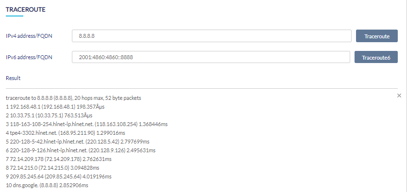
Performing a Traceroute Test
- Navigate to Monitor > Gateway > Devices and select a device from the list.
- Select the Tools tab in the top-right of the screen.
- Under Traceroute, enter a valid IP address or FQDN in the IP address/FQDN field.
- Click Traceroute for IPv4 addresses or Traceroute6 for IPv6 addresses of the remote hosts. The results will be displayed as shown below:
Performing LED Blinking and Device Reboot
- Navigate to Monitor > Gateway > Devices and select a device from the list.
- Select the Tools tab in the top-right of the screen.
- In the Others section, click Reboot to reboot the device. Or click Start to start blink LEDs on the device. Click Stop to top blinking LEDs.

Note: Please refer to the respective device's manual for the status of LED indicators.
Performing WAN Throughput Test
- Navigate to Monitor > Gateway > Devices and select a device from the list.
- Select the Tools tab at the top right of the screen.
- In the WAN Throughput section, click Go. The upload and download speed will be displayed.

Exporting or Importing Device Settings
The device setting metadata can be exported as a single CSV file and it can be later imported for configuration restoration. To export device settings:
- Navigate to Monitor > Gateway > Devices and select a device from the list.
- Select the Tools tab at the top right of the screen.
- In the Export and Import Device Settings section, click Download. The exported file will be downloaded to your browser's default download folder.
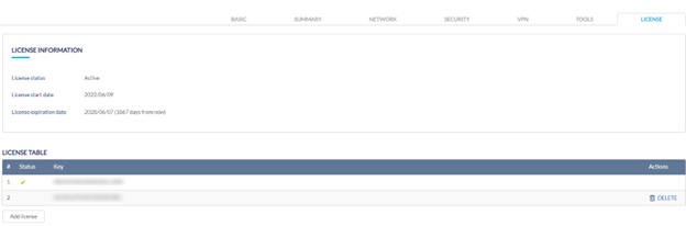
License
Adding a License Key to a Device
- Navigate to Monitor > Gateway > Devices and select a device from the list.
- Select the License tab in the top-right of the screen.
- In the License Table section, click Add License.
- Enter a valid license key.
- Click Save.
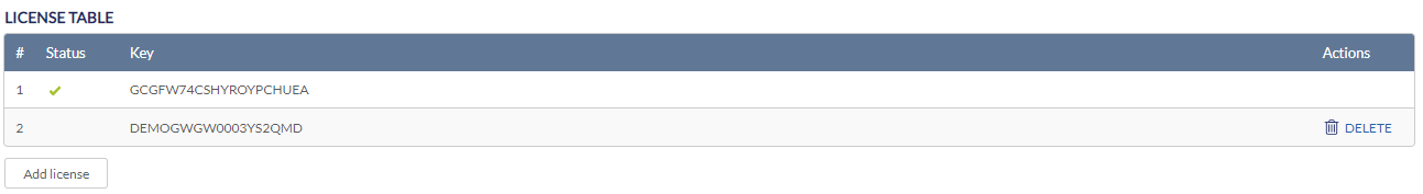
Deleting a License Key From a Device
- Navigate to Monitor > Gateway > Devices and select a device from the list.
- Select the License tab in the top-right of the screen.
- In the License Table section, from the license key list, click Delete under the Actions column of the license key you wish to delete.
- When prompted to confirm, click Yes.
Note: Deleting a license key from a device will reclassify it as Unused in the license management inventory.