Profiles
Profiles are a set of general configuration settings that can be swiftly and easily applied to all devices associated with the Profile so all devices are configured identically as a group.
Creating a Profile
After a profile is created, you can configure switch port functionality, port activity schedules, and advanced features including VLAN, Quality of Service, and access control functions in each profile.
Note: Profiles are created for individual organizations. In order to configure Profiles, select the organization from the drop-down menu at the top of the page.
- Navigate to Configure > Switch > Profiles.
- Click Create Profile.
- Enter a name for the Profile and choose the device model.
Note: The Profile can only be used for the selected device model type. - Select the Access Level for the accessibility level of the profile.
- [Optional] Select Clone from existing profile and choose a Profile from the drop-down menu to clone an existing Profile.
- Click Create Profile.
Deleting Profiles
- Navigate to Configure > Switch > Profiles.
- Click the checkbox next to the Profiles you wish to delete.
- From the Profile list, click Delete profile at the top of the table.
- When prompted to confirm, click Yes.
Configuring Switch Port Settings
From the Ports window, you can configure basic and advanced settings for individual ports or groups of ports. Switch ports are categorized into group ports, with each group referring to the number of ports on the physical switch model. For example, port group 10 configures port settings for 10-port switches. The port settings configured in the profile will only apply to the ports of the corresponding switch type. For example, any port configurations for port group 10 will only apply to corresponding ports on 10-port switch using this profile.
Customizing the Profile Port Configuration Overview
- Navigate to Configure > Switch > Profiles.
- From the Profile list, click Ports under the Actions column of the Profile you wish to edit.
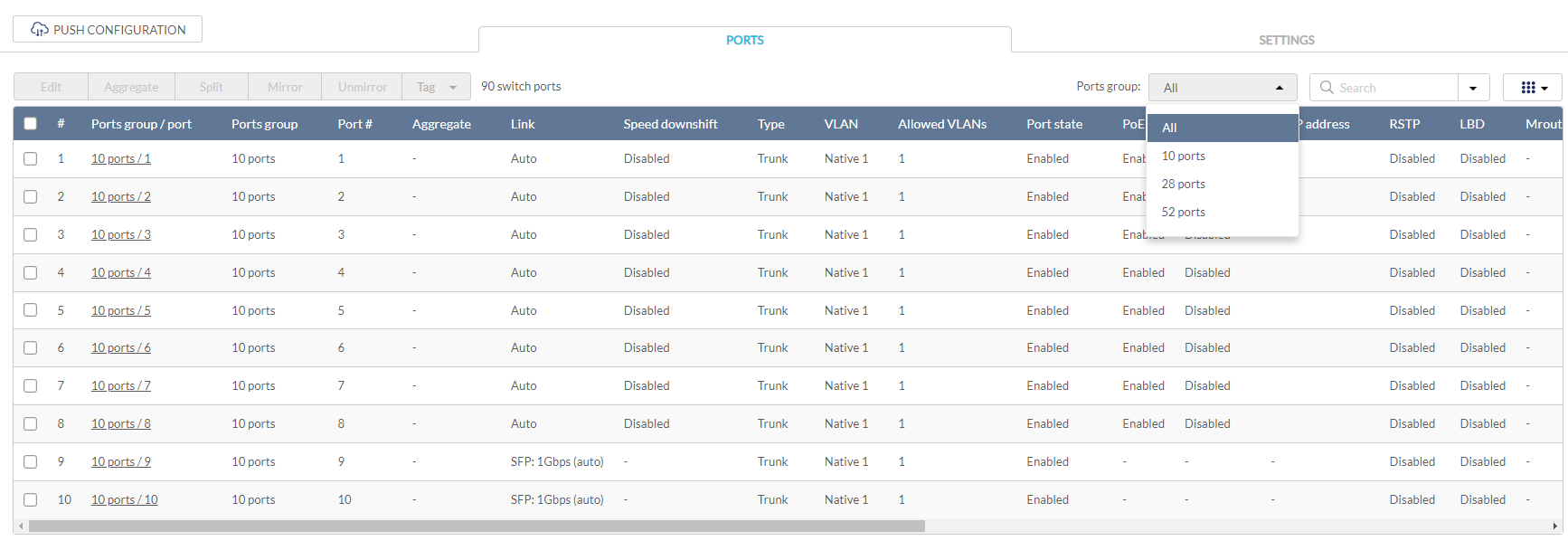
- Select a port group from the Ports group drop-down menu. This will only display ports for the selected port group profile. For example, selecting port group 28 will only show ports 1 to 28 of the profile used for 28-port switches. Select All to show all port groups.
- Click the filter parameter icon.
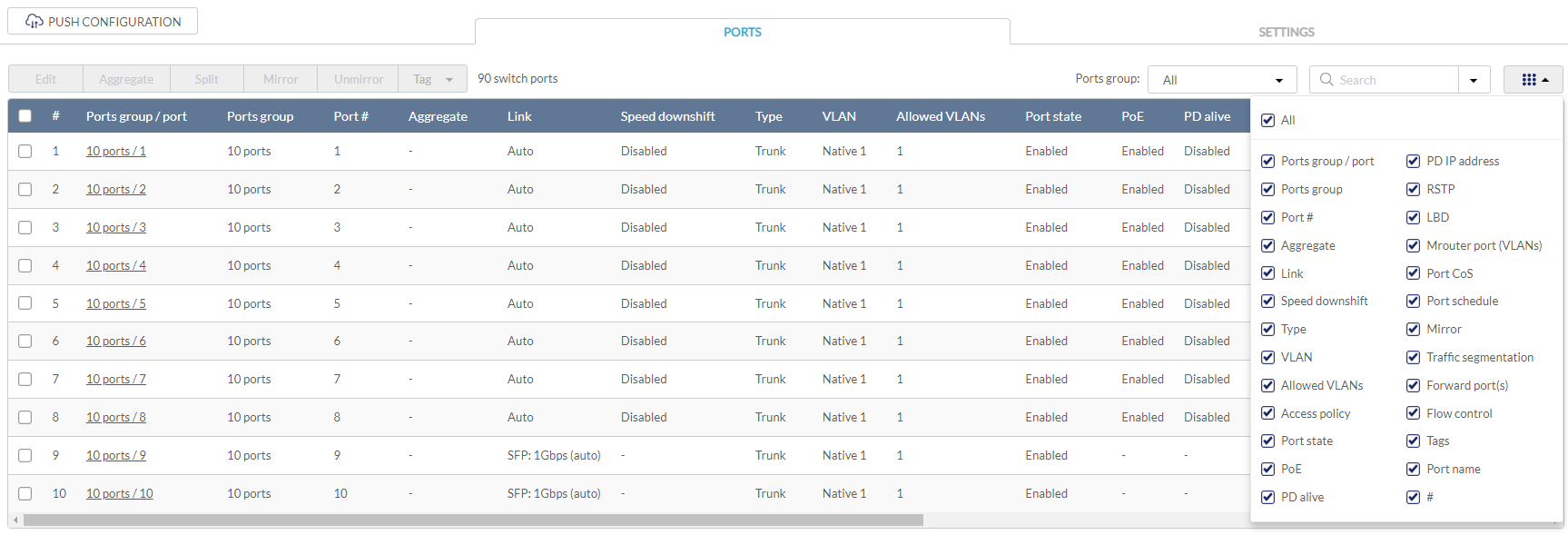
- Click the checkbox next to the parameters to display them in the overview.
Note: All checked parameters will automatically appear.
Configuring Profile Port Settings for One or More Switch Ports
Switch port configuration allows administrators to configure extensive port functionality including port availability, port speed, redundancy, VLAN, PoE, and port activity schedules for individual ports or for a group of ports.
- Navigate to Configure > Switch > Profiles.
- From the Profile list, click Ports under the Actions column of the Profile you wish to edit.
- From the port list, check the box next to the ports you wish to edit.
- Click Edit.
- Specify the following information:
Note: At the top of the edit port window is a list of all selected ports. The changes made will apply to all selected ports.
|
Port name |
Enter a name for the port. If multiple ports are selected, this name will be applied to all ports. |
|
Port state |
Choose to enable or disable the port. |
|
Choose to enable or disable RSTP. Note: RSTP cannot be used in conjunction with LBD. Note: User must enable Profile/Settings/STP Configuration for this port to enable RSTP |
|
|
STP guard |
If RSTP is enabled, choose the guard type. Disabled: Do not use root guard enhancement. Root guard: Root guard enhancement allows administrators to define the position of the root bridge port in the network. |
|
Choose to enable or disable LBD. Note: LBD cannot be used in conjunction with RSTP. |
|
| Port CoS | Select the Class of Service (CoS) value (0-7) to mark the packets transmitting out of this port. |
|
Type |
Choose the function type of the port. Trunk: Sends and receives tagged data from different VLANs. Access: Only sends and receives untagged data from the VLAN the port belongs to. |
|
Native VLAN |
Enter the ID of the native VLAN the port belongs to if the Trunk type is selected. |
|
Allowed VLANs |
Enter the IDs of the VLANs that can route traffic through this port if the Trunk type is selected. Enter All to allow all traffic from all VLANs to pass through this port. |
| Access VLAN | Enter the ID of the VLAN the port belongs to if the Access type is selected. |
| Access Policy | Select the Access Policy for this port if the Access type is selected. The options include Disabled, MAC Whitelist, Port Security Delete-on-Time Mode, and Port Security Permanent Mode. |
| Static Whitelisted MACs | Enter the MAC addresses that can access this port to restrict access to this port to devices with specific MAC addresses. If entering multiple MAC addresses, enter only one address per line. |
| Dynamic Whitelist Size Limit |
Enter the maximum number of allowed MAC addresses that the device should learn dynamically for the Port Security Delete-on-time Mode or Port Security Permanent Mode. |
| Dynamic Whitelisted MACs |
Display the learned MAC addresses for the Port Security Delete-on-time mode and Port Security Permanent Mode. |
|
Tags |
Enter a descriptive tag for the port. Multiple tags can be entered. If multiple ports are selected, any tags will be applied to all ports. |
|
Link (RJ45) |
Choose the maximum link speed of the port. Select Auto to allow the port to auto-negotiate port speed with the partner port or device. |
|
Link (SFP) |
Choose the maximum link speed of the port. Select Auto to allow the port to auto-negotiate port speed with the partner port or device. |
| Speed downshift |
Enables/disables automatic speed downshift on the supported interface when the designated maximum speed cannot be established. |
|
Choose to enable or disable Power over Ethernet (PoE) functionality on this port. Note: The PoE setting will only apply to ports that support Power over Ethernet. |
|
| PD Alive | Enable or disable the automatic detection of the Powered Devices status. |
| PD IP address | Enter the IP address of the Powered Device. |
|
Port Schedule |
Choose a port schedule. Port schedules are separately configured. Refer to the Creating a Switch Port Schedule section. |
| Traffic segmentation | Enable or disable traffic segmentation on this port to further restrict traffic flow in your network. If enabled, select the forward ports. |
| Forward Ports | Select the forward ports if traffic segmentation is enabled. |
| Flow control | Enable or disable the flow control on the port to regulate the data transfer rate between two devices. |
- Click Save.
- Click Push Configuration.
Aggregating Multiple Switch Profile Ports
Port aggregation allows you to link multiple physical ports together as one logical link to increase port bandwidth and redundancy in the event of a single physical link failure. Ports can be aggregated using either LACP or static link.
Note: Port aggregation is not supported if the port type is set to “Access”. To configure the port type, refer to the above Configuring Profile Port Settings for One or More Switch Ports section for more information.
- Navigate to Configure > Switch > Profiles.
- From the Profile list, click Ports under the Actions column of the Profile you wish to edit.
- From the port list, check the box next to the ports you wish to link together.
- Click Aggregate.
- In the Link Aggregation Setting window, select the aggregation type.
Note: Static link requires manual configuration of the ports in the aggregation group. Link Aggregation Control Protocol (LACP) dynamically queries to listening ports to join the aggregation group.
|
LACP (Link Aggregation Control Protocol) allows the switch to automatically detect links in a port trunk group. |
|
|
Static |
Static link aggregation. |
- Click Aggregate.
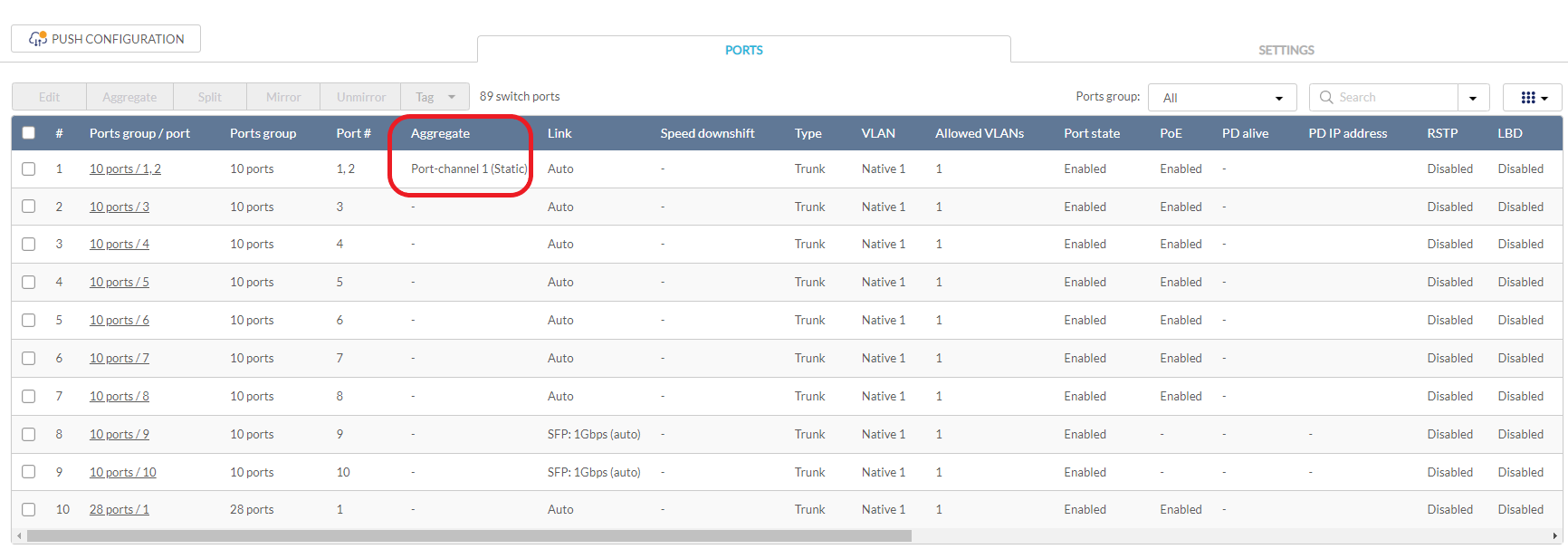
Note: Aggregated ports can be identified by the combined port number in the Aggregate column of the port overview.
- Click Push Configuration.
Splitting Aggregated Switch Ports
Linked port groups can be split into their respective individual ports. Splitting port groups will undo all aggregation settings applied to the affected ports.
- Navigate to Configure > Switch > Profiles.
- From the Profile list, click Ports under the Actions column of the Profile you wish to edit.
- From the port list, check the box next to the aggregated port(s) you wish to split.
- Click Split.
Note: This will immediately split the selected aggregated ports. - Click Push Configuration.
Mirroring Port Traffic to Another Switch Profile Port
Port Mirroring is a method of monitoring network traffic that forwards a copy of each incoming and/or outgoing packet from one port of the switch to another port, where the packet can be studied. This enables network managers to better monitor network performance.
- Navigate to Configure > Switch > Profiles.
- From the Profile list, click Ports under the Actions column of the Profile you wish to edit.
- From the port list, check the box next to the port(s) you wish to mirror.
- Click Mirror.
- Specify the following information:
|
Source ports |
Select the data to mirror from the drop-down menu for each selected port. Both: Mirror both incoming and outgoing. Rx: Mirror only data received on the port. Tx: Mirror only data transmitted by the port. |
|
Destination port |
Enter the port number of the destination port. |
- Click Create port mirror.
- Click Push Configuration.
Undoing Port Traffic Mirroring
- Navigate to Configure > Switch > Profiles.
- From the Profile list, click Ports under the Actions column of the Profile you wish to edit.
- From the port list, check the box next to the mirrored port(s) you wish to unmirror.
- Click Unmirror.
- Click Delete port mirror.
- Click Push Configuration.
Adding a Tag to One or More Switch Profile Ports
User can add descriptive tag to ports to identify and filter different ports or groups of ports. Tags are purely informational and do not affect the functionality of the port.
- Navigate to Configure > Switch > Profiles.
- From the Profile list, click Ports under the Actions column of the Profile you wish to edit.
- From the port list, check the box next to the port(s) you wish to add a tag to.
- Click Tag.
- In the Add field, enter the tag content. Multiple tags can be entered.
Note: If this is a new tag, click Add option to make this a reusable tag.
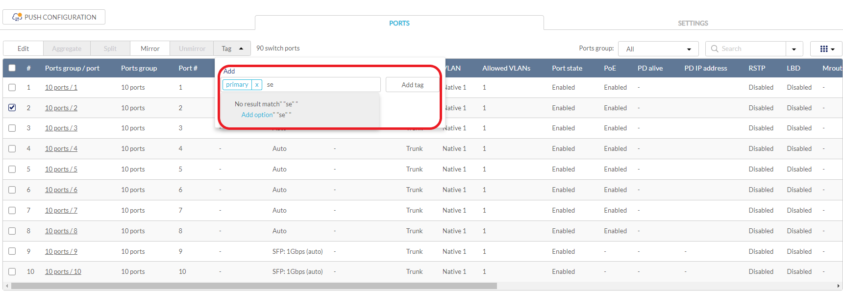
- Click Add tag.
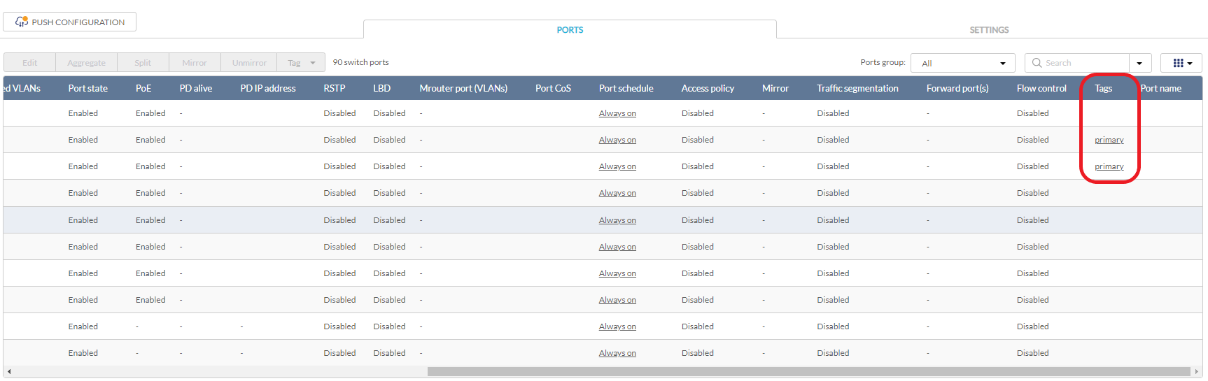
Note: Any tags associated to a port will be shown in the Tags column.
Removing a Tag From One or More Switch Ports
- Navigate to Configure > Switch > Profiles.
- From the Profile list, click Ports under the Actions column of the Profile you wish to edit.
- From the port list, check the box next to the tagged port(s) you wish to remove the tag(s) from.
- Click Tag.
- In the Delete field, enter the tag name. Alternatively, click the input field to bring up a list with all the associated tags.
- Click Remove tag.
Configuring Basic Switch Profile Settings
Configuring Management VLAN Membership
The management VLAN is the primary VLAN to connect to the cloud to configure and manage the network. By default, management VLAN 1 is the default for all switch ports.
- Navigate to Configure > Switch > Profiles.
- From the Profile list, click Settings under the Actions column of the Profile you wish to edit.
- Click the Basic tab.
- In the VLAN Configuration section, select a VLAN ID from the drop-down menu or directly enter an ID into the VLAN ID field.
Note: Changing the management VLAN ID requires the management port(s) to be assigned to the new management VLAN ID. - Click Save.
- Click Push Configuration.
Configuring Spanning Tree Protocol (STP)
RSTP is an availability and redundancy feature that prevents redundant backup links between switches and prevents switch loops from forming by shutting down the port causing the loop. If RSTP is enabled under profile settings, this profile’s device will be enabled. You can enable/disable RSTP of individual ports under the Switch Ports page, or at Configure > Switch > Profile > Ports. Note: RSTP must be manually enabled under BOTH Switch Settings of a profile and Switch Ports.
- Navigate to Configure > Switch > Profiles.
- From the Profile list, click Settings under the Actions column of the Profile you wish to edit.
- Click the Basic tab.
- In the RSTP Configuration section, select Enable next to RSTP.
- Click Add to add an RSTP bridge priority.
- In the Set the bridge priority for switches window, specify the following information:
|
Switch |
Enter the name of the switch or click the field and select an available switch from the drop-down menu. |
|
Bridge Priority |
Select a priority value from the drop-down menu. Lower values are more likely to act as the root, while higher values are more likely to act as edges. |
- [Optional] Click Add to add additional bridge priorities.
- Click Add.
- [Optional] To delete a bridge priority, check the checkbox next to the switch and click Delete under the Actions column.
- Click Save.
- Click Push Configuration.
Configuring DHCP Server Screening
DHCP screening allows administrators to whitelist DHCP servers to prevent unauthorized DHCP servers and devices from gaining access to the network.
- Navigate to Configure > Switch > Profiles.
- From the Profile list, click Settings under the Actions column of the Profile you wish to edit.
- Click the Basic tab.
- In the DHCP Server Screening Configuration section, select Enable next to DHCP Server Screening.
- In the Allowed DHCP server field, enter the IP address of the DHCP server to whitelist.
Note: Up to 5 DHCP servers can be whitelisted. - Click Save.
- Click Push Configuration.
Configuring Voice VLAN
Voice traffic from IP phones can be assigned to a dedicated VLAN (via Voice VLAN ID setting) and given traffic priority (via Voice VLAN CoS setting).
Note: Voice VLAN priority settings overrule any priority settings configured in the Quality of Service section.
Note: Voice VLAN is not supported if the port type is set to “Trunk”.
- Navigate to Configure > Switch > Profiles.
- From the Profile list, click Settings under the Actions column of the Profile you wish to edit.
- Click the Basic tab.
- In the Voice VLAN Configuration section, select Enable next to Voice VLAN.
- In the Voice VLAN ID field, enter an ID between 2 and 4094.
- Select a Voice VLAN Class of Service (CoS) level from the drop-down menu.
Note: The CoS level reflects the priority level of Voice VLAN traffic. A higher value means a high priority, whereas a lower value means a low priority. - [Optional] Click Add to add a Voice VLAN OUI.
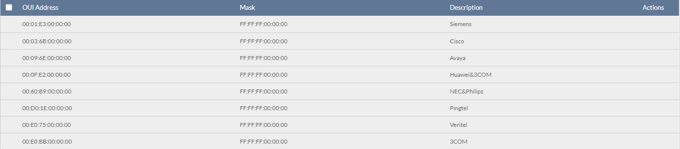
Note: An Organizationally Unique Identifier (OUI) is used to add additional manufacturers to the voice VLAN identification list in addition to the pre-configured OUIs. - In the Add OUIs for switches window, specify the following information:
|
OUI Address |
This field will contain which MAC address range the OUI mask will begin with. |
|
Mask |
With the same concept of subnet mask, OUI Mask uses “F” as match, while ”0” as any. |
|
Description |
Add a description for the OUI. |
- [Optional] Click Add to add additional OUIs.
- Click Add.
- [Optional] To delete an OUI, check the checkbox next to the OUI and click Delete.
Note: Default OUIs cannot be deleted. - Click Save.
- Click Push Configuration.
Configuring Jumbo Frame
Enabling Jumbo Frame allows the port to switch frames larger than the standard Ethernet frame and can maximize server-to-server performance.
- Navigate to Configure > Switch > Profiles.
- From the Profile list, click Settings under the Actions column of the Profile you wish to edit.
- Click the Basic tab.
- In the Jumbo Frame Configuration section, select Enable next to Jumbo Frame.
- Click Save.
- Click Push Configuration.
Configuring Quality of Service Settings
QoS is an implementation of the IEEE 802.1p standard that allows network administrators to reserve bandwidth for important functions that require a larger bandwidth or that might have a higher priority, such as VoIP (voice-over Internet Protocol), web browsing applications, file server applications or video conferencing. By reserving more bandwidth for critical traffic, the overall network performance can be maintained and critical data can be transmitted smoothly.
The Quality of Service windows displays the status of Quality of Service priority levels of each port, a higher priority means the traffic from this port will be first handled by the switch. For packets that are untagged, the switch will assign the priority depending on your configuration.
- Navigate to Configure > Switch > Profiles.
- From the Profile list, click Settings under the Actions column of the Profile you wish to edit.
- Click the Basic tab.
- In the Quality of Service section, select the Trust State. The selection determines the CoS value assignment method. For CoS/802.1p, the CoS will be based on the packet's Queue ID. For DSCP, the CoS will be based on the DSCP value. Configure the mapping between Queue ID and CoS and between CoS and DSCP below for your selection.
- Select the Scheduling method: SP (Strict Priority) and WRR (Weighted Round Robin. For SP, incoming traffic with the highest priority will be transmitted first. For WRR, the proportion of the incoming packets to be transmitted will be based on the weight of the queue.
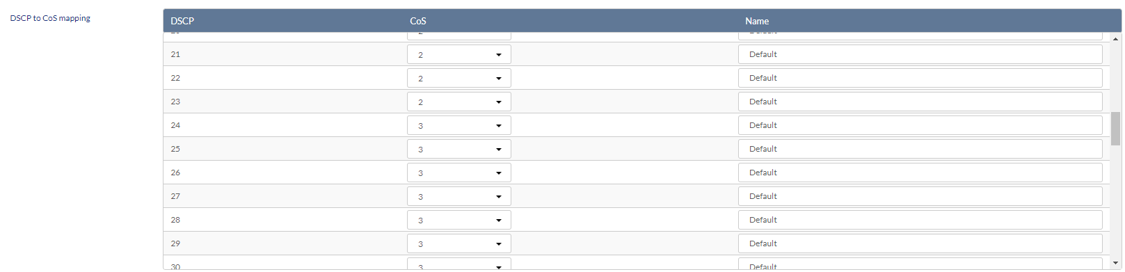
- In the DSCP to CoS Mapping section, select a Class of Service value between 0 to 7 for each DSCP value. A higher value means a higher priority while a lower value means a lower priority. Depending on the Scheduling Method, Traffic from ports with assigned CoS values are processed differently.
- In the CoS to Queue Mapping section, select the Queue ID to for each CoS value (0-7).
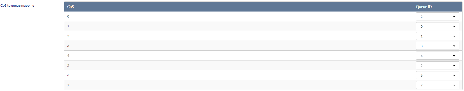
- Click Save.
- Click Push Configuration.
Configuring SNMP Settings
Simple Network Management Protocol (SNMP) can be enabled to support monitoring and management tasks on the network. Depending on the capabilities of the switch, versions v1, v2c and v3 are supported. Once it is enabled, the switch device can then reply to the SNMP commands and generate trap messages when there are alert events.
- Navigate to Configure > Switch > Profiles.
- From the Profile list, click Settings under the Actions column of the Profile you wish to edit.
- Click the Basic tab.
- In the SNMP section, enable or disable the SNMP.
- Enter the UDP port for SNMP communication. The default is 161.
- Enter the SNMP community name. The default is public.
- Enable or disable the trap state. If enabled, enter the trap receivers' IP addresses. Separate multiple addresses with a comma, space , or semicolon.
- [Optional] Click Download MIBs to download MIB files. You can view them with a MIB browser.
- Click Save.
- Click Push Configuration.
Configuring ACL Settings
Creating IPv4 Access Control Policy Rules
IPv4 Access Control Lists (ACL) allow administrators to configure a set of criteria for permitting or denying traffic coming from and to the switch based on IP addresses.
- Navigate to Configure > Switch > Profiles.
- From the Profile list, click Settings under the Actions column of the Profile you wish to edit.
- Click the ACL tab.
- In the User Defined IPv4 Rules section, click Add.
- In the Add an IPv4 rule window, specify the following information:
| Sequence No. | Enter a sequence number for the ACL for proper positioning of the entry. |
|
Policy |
Select an access policy. Deny: Traffic with matching parameters will be denied. |
|
Protocol |
Select a protocol from the drop-down menu. UDP: The rule only applies to traffic with a UDP header. TCP: The rule only applies to traffic with a TCP header. |
|
Source |
Enter the source IP address. If the source address is configured as Any, all source traffic will be evaluated according to the conditions of the rule. |
|
Src port |
Specify the source port number between 0 and 65535. If the source port is configured as Any, all source ports will be evaluated according to the conditions of the rule. |
|
Destination |
Enter the destination IP address. If the destination address is configured as Any, all destination traffic will be evaluated according to the conditions of the rule. |
|
Dst port |
Specify the destination port number between 0 and 65535. If the source port is configured as Any, all destination ports will be evaluated according to the conditions of the rule. |
| VLAN | Specify the VLAN ID of the traffic. If it is configured as Any, all VLANs will be evaluated according to the conditions of the rule. |
|
Comment |
Enter a description for the rule. |
- Click Add.
- Click Save.
- Click Push Configuration.
Editing IPv4 Access Control Policy Rules
- Navigate to Configure > Switch > Profiles.
- From the Profile list, click Settings under the Actions column of the Profile you wish to edit.
- Click the ACL tab.
- In the User Defined IPv4 Rules section, click Edit in the Actions column of the rule you wish to edit.
- Specify the following information:
| Sequence No. | Enter a sequence number for the ACL for proper positioning of the entry. |
|
Policy |
Select an access policy. Deny: Traffic with matching parameters will be denied. |
|
Protocol |
Select a protocol from the drop-down menu. UDP: The rule only applies to traffic with a UDP header. TCP: The rule only applies to traffic with a TCP header. |
|
Source |
Enter the source IP address. If the source address is configured as Any, all source traffic will be evaluated according to the conditions of the rule. |
|
Src port |
Specify the source port number between 0 and 65535. If the source port is configured as Any, all source ports will be evaluated according to the conditions of the rule. |
|
Destination |
Enter the destination IP address. If the destination address is configured as Any, all destination traffic will be evaluated according to the conditions of the rule. |
|
Dst port |
Specify the destination port number between 0 and 65535. If the source port is configured as Any, all destination ports will be evaluated according to the conditions of the rule. |
| VLAN | Specify the VLAN ID of the traffic. If it is configured as Any, all VLANs will be evaluated according to the conditions of the rule. |
|
Comment |
Enter a description for the rule. |
- Click Save.
- Click Push Configuration.
Deleting IPv4 Access Control Policy Rules
- Navigate to Configure > Switch > Profiles.
- From the Profile list, click Settings under the Actions column of the Profile you wish to edit.
- Click the ACL tab.
- In the User Defined IPv4 Rules section, click the checkbox next to the rule(s) you wish to delete.
- Click Delete.
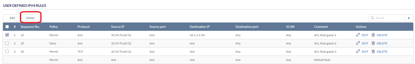
- When prompted to confirm, click Yes.
Creating MAC Access Control Policy Rules
Besides ACL filtering according to IP addresses, MAC addresses can also be configured and applied to ACL.
- Navigate to Configure > Switch > Profiles.
- From the Profile list, click Settings under the Actions column of the Profile you wish to edit.
- Click the ACL tab.
- In the User Defined MAC Rules section, click Add.
- In the Add a MAC ACL window, specify the following information:
| Sequence No. | Enter a sequence number for the ACL for proper positioning of the entry. |
|
Policy |
Select an access policy. Deny: Traffic with matching parameters will be denied. |
| Ethernet Type | Enter the Ethernet type using the hex value, for example, 0x0-0xffff. Enter Any for all Ethernet types. |
|
Source MAC |
Enter the source MAC address. If the source address is configured as Any, all source traffic will be evaluated according to the conditions of the rule. |
|
Destination MAC |
Enter the destination MAC address. If the destination address is configured as Any, all destination traffic will be evaluated according to the conditions of the rule. |
| CoS | Enter the Class of Service value (0-7). Enter Any if all CoS should be evaluated. |
| VLAN | Specify the VLAN ID of the traffic. If it is configured as Any, all VLANs will be evaluated according to the conditions of the rule. |
|
Comment |
Enter a description for the rule. |
- Click Save.
- Click Push Configuration.
Configuring Access Policies
Creating an Access Policy
Administrators can configure one or more remote RADIUS servers for port-based or MAC-based authorization and authentication. This ensures that only users with matching credentials have access to the network. Administrators can also configure a Guest VLAN to grant Internet access to visitors, while preventing them from accessing the network.
- Navigate to Configure > Switch > Profiles.
- From the Profile list, click Settings under the Actions column of the Profile you wish to edit.
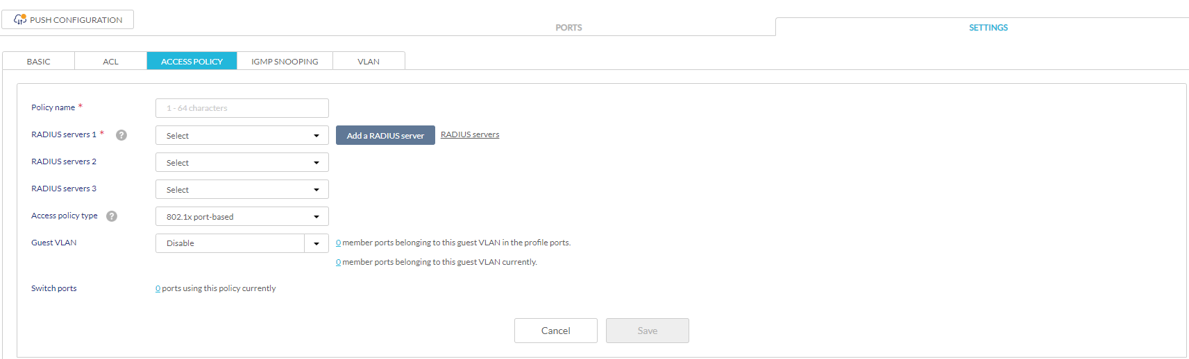
- Click the Access Policy tab.
- Enter a name for the policy.
- In the RADIUS servers field, select a pre-configured RADIUS server or click Add a RADIUS server to add a new RADIUS server.
- In the Add RADIUS servers window, specify the following information:
| Server Name | Enter a name for the RADIUS server. |
|
IP address |
Enter the IP address of the RADIUS server. |
|
Port |
Enter a port for the RADIUS server. The range is between 1 and 65535 and default is 1812. |
| Authentication method | Select an authentication method: Password Authentication Protocol (PAP), Challenge-Handshake Authentication Protocol (CHAP), Microsoft Challenge-Handshake Authentication Protocol (MS-CHAP), MS-CHAPv2, or Extensible authentication protocol Message-digest algorithm (EAP-MD5) . |
|
Secret |
Enter a shared secret. |
| RADIUS Accounting | Enable or disable RADIUS accounting. Note that this feature depends on the features of the device model. |
Note: RADIUS servers can be configured centrally in the Authentication menu. Refer to Authentication for more information.
- [Optional] Click RADIUS server 2/RADIUS server 3 to add additional RADIUS servers.
- Select an access policy type:
|
802.1x port-based |
This method requires only one user to be authenticated per port by a remote RDIUS server to allow the remaining users on the same port to access the network. |
|
802.1x MAC-based |
Using this method, the Switch will automatically learn up to a maximum of 512 MAC addresses by port and set them in a list. Each MAC address must be authenticated by the Switch using a remote RADIUS server before being allowed access to the Network. Note: DBS-2000 can support a total number of IPv4 and MAC rules of 512 (go to the ACL tab of the profile setting) and 256 for the total number of users for authentication. |
- [Optional] Select a VLAN ID for guest VLAN from the drop-down menu.
- Click Save.
- Click Push Configuration.
Configure a Guest VLAN
Administrators can configure one or more Guest VLANs to grant internet access to visitors, while preventing them from accessing the network.
- Navigate to Configure > Switch > Profiles.
- From the Profile list, click Settings under the Actions column of the Profile you wish to edit.
- Click the Access Policy tab.
- Select a Guest VLAN from the list.
- Click Save.
- Click Push Configuration.
Configuring Internet Group Management Protocol (IGMP) Snooping
IGMP Snooping allows administrators to configure switches to subscribe to, and receive multicast traffic. If a switch is not added to the IGMP list, it will not receive multicast traffic by default.
- Navigate to Configure > Switch > Profiles.
- From the Profile list, click Settings under the Actions column of the Profile you wish to edit.
- Click the IGMP Snooping tab.
- Click Add to add a switch to the IGMP snooping list.
- In the Add IGMP snooping settings for switches window, specify the following information:
|
Switch |
Enter the name of the switch or click the field and select an available switch from the drop-down menu. |
|
IGMP Snooping |
Select an IGMP policy. Enable: The switch will subscribe to and receive multicast traffic. Disable: The switch will not receive multicast traffic. |
- [Optional] Click Add to add switches to the IGMP list.
- Click Add.
- To configure IGMP snooping VLAN settings, click Add.
Enter the following information:
VLAN ID
Assign a VLAN ID for the IGMP VLAN group.
IGMP Snooping
Select an IGMP policy.
Enable: The VLAN will subscribe to and receive multicast traffic.
Disable: The VLAN will not receive multicast traffic.
Querier state Enable or disable the Querier state for sending query messages to discover members of a given multicast group. Multicast filtering mode - Select the filtering mode for multicast: Forward unregistered or Filter unregistered.
Static Mrouter port settings Select the member ports of the configured VLAN to set as a Static Multicast router (Mrouter) port which connects to a multicast router for forwarding multicast traffic. - Click Save.
- Click Push Configuration.
Viewing Current VLANs on the Switch
The configured VLANs can be viewed in the Profile settings. To obtain the VLAN list, go to Configure > Switch > Profiles.
- Navigate to Configure > Switch > Profiles.
- From the Profile list, click Settings under the Actions column of the Profile you wish to view or edit.
- Click the VLAN tab.
The following information is displayed:
|
VLAN ID |
The VLAN ID. |
| VLAN Type | Shows the VLAN type: Management VLAN, Voice VLAN, or Guest VLAN. If it is not specified, it is regular VLAN. |
| Tagged member ports/Untagged member ports | Shows the member ports' VLAN type. |
|
IGMP Snooping Status |
Shows the IGMP status for the VLAN. Enabled: The VLAN will subscribe to and receive multicast traffic. Disabled: The VLAN will not receive multicast traffic. |
Pushing Configuration Changes
The Push Configuration function allows you to quickly apply Profile configuration changes to all devices using this Profile.
Note: Changes made to a Profile’s ports or settings will be pushed to all associated devices after the user selects Push Configuration.
- Navigate to Configure > Switch > Profiles.
- From the Profile list, click the checkbox next to the Profiles you wish to push the configuration to apply it to the associated devices of the configured model.
- Click Push Configuration at the top of the table.
- Select either Push Configuration Now or Schedule a Configuration Pushing Time to apply the configuration changes at a later time. The schedule will be reflected in the Scheduled Push column of the Profiles list.
Note: A result window will appear providing a summary of the update status.
- In the Push Configuration Result window, click the X icon in the top-right to close the window.